| Last Modified: 08-21-2023 | 6.11:8.1.0 | Doc ID: RM100000001PY58 |
| Model Year Start: 2021 | Model: Avalon HV | Prod Date Range: [08/2020 - ] |
| Title: CELLULAR COMMUNICATION: SAFETY CONNECT SYSTEM: B15C511,B15C513; Emergency Call Switch Circuit Short to Ground; 2021 - 2022 MY Avalon Avalon HV [08/2020 - ] | ||
|
DTC |
B15C511 |
Emergency Call Switch Circuit Short to Ground |
|
DTC |
B15C513 |
Emergency Call Switch Circuit Open |
DESCRIPTION
If the DCM (telematics transceiver) detects an error in the communication between the DCM (telematics transceiver) and the roof console box sub-assembly (manual (SOS) switch) as a result of the DCM (telematics transceiver) self check, this DTC will be stored.
|
DTC No. |
Detection Item |
DTC Detection Condition |
Trouble Area |
|---|---|---|---|
|
B15C511 |
Emergency Call Switch Circuit Short to Ground |
Manual (SOS) switch impedance (Ω) is lower than the malfunction threshold for 10 seconds or more when the ignition switch is ON |
|
|
B15C513 |
Emergency Call Switch Circuit Open |
Manual (SOS) switch impedance (Ω) is higher than the malfunction threshold for 10 seconds or more when the ignition switch is ON |
|
WIRING DIAGRAM
w/ Sliding Roof
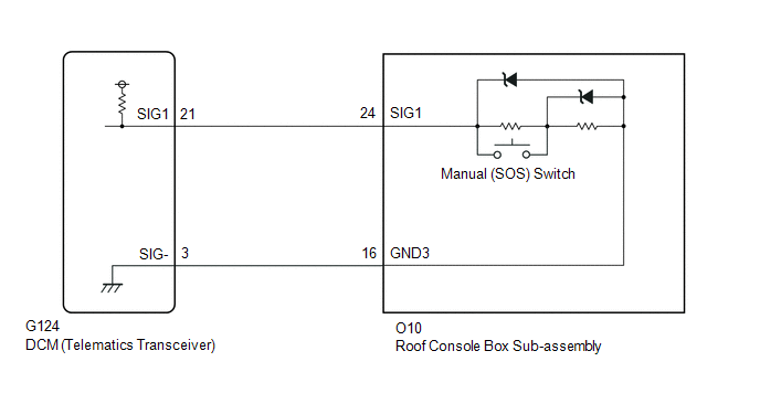
w/o Sliding Roof

CAUTION / NOTICE / HINT
NOTICE:
Depending on the parts that are replaced during vehicle inspection or maintenance, performing initialization, registration or calibration may be needed. Refer to Precaution for Safety Connect System.
Click here
![2021 MY Avalon Avalon HV [08/2020 - 08/2021]; CELLULAR COMMUNICATION: SAFETY CONNECT SYSTEM: PRECAUTION](/t3Portal/stylegraphics/info.gif)
PROCEDURE
|
1. |
CHECK DTC |
(a) Turn the ignition switch off.
(b) Connect the GTS to the DLC3.
(c) Turn the ignition switch to ON and wait for 10 seconds or more.
(d) Turn the GTS on.
(e) Clear the DTCs.
Body Electrical > Telematics > Clear DTCs
(f) Check for DTCs and check that no DTCs are output.
Body Electrical > Telematics > Trouble Codes
OK:
No DTCs are output.
| OK |

|
|

|
2. |
CONFIRM MODEL |
(a) Choose the model to be inspected.
|
Result |
Proceed to |
|---|---|
|
w/ Sliding Roof |
A |
|
w/o Sliding Roof |
B |
| B |
|
|
|
3. |
INSPECT ROOF CONSOLE BOX SUB-ASSEMBLY (MANUAL (SOS) SWITCH) |
|
(a) Remove the roof console box sub-assembly (manual (SOS) switch). Click here
|
|
(b) Measure the resistance according to the value(s) in the table below.
Standard Resistance:
|
Tester Connection |
Condition |
Specified Condition |
|---|---|---|
|
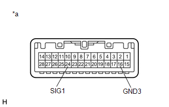
24 (SIG1) - 16 (GND3) |
Manual (SOS) switch not operated |
410 to 414 Ω |
|
24 (SIG1) - 16 (GND3) |
Manual (SOS) switch operated |
81 to 83 Ω |
| NG |
|
|
|
4. |
CHECK HARNESS AND CONNECTOR (DCM (TELEMATICS TRANSCEIVER) - ROOF CONSOLE BOX SUB-ASSEMBLY (MANUAL (SOS) SWITCH)) |
(a) Disconnect the G124 DCM (telematics transceiver) connector.
(b) Disconnect the O10 roof console box sub-assembly (manual (SOS) switch) connector.
(c) Measure the resistance according to the value(s) in the table below.
Standard Resistance:
|
Tester Connection |
Condition |
Specified Condition |
|---|---|---|
|
G124-21 (SIG1) - O10-24 (SIG1) |
Always |
Below 1 Ω |
|
G124-3 (SIG-) - O10-16 (GND3) |
Always |
Below 1 Ω |
|
G124-21 (SIG1) or O10-24 (SIG1) - Body ground |
Always |
10 kΩ or higher |
|
G124-3 (SIG-) or O10-16 (GND3) - Body ground |
Always |
10 kΩ or higher |
| OK |
|
| NG |
|
REPAIR OR REPLACE HARNESS OR CONNECTOR |
|
5. |
INSPECT ROOF CONSOLE BOX SUB-ASSEMBLY (MANUAL (SOS) SWITCH) |
|
(a) Remove the roof console box sub-assembly (manual (SOS) switch). Click here
|
|
(b) Measure the resistance according to the value(s) in the table below.
Standard Resistance:
|
Tester Connection |
Condition |
Specified Condition |
|---|---|---|
|
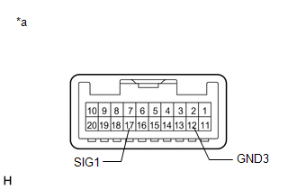
17 (SIG1) - 12 (GND3) |
Manual (SOS) switch not operated |
410 to 414 Ω |
|
17 (SIG1) - 12 (GND3) |
Manual (SOS) switch operated |
81 to 83 Ω |
| NG |
|
|
|
6. |
CHECK HARNESS AND CONNECTOR (DCM (TELEMATICS TRANSCEIVER) - ROOF CONSOLE BOX SUB-ASSEMBLY (MANUAL (SOS) SWITCH)) |
(a) Disconnect the G124 DCM (telematics transceiver) connector.
(b) Disconnect the O9 roof console box sub-assembly (manual (SOS) switch) connector.
(c) Measure the resistance according to the value(s) in the table below.
Standard Resistance:
|
Tester Connection |
Condition |
Specified Condition |
|---|---|---|
|
G124-21 (SIG1) - O9-17 (SIG1) |
Always |
Below 1 Ω |
|
G124-3 (SIG-) - O9-12 (GND3) |
Always |
Below 1 Ω |
|
G124-21 (SIG1) or O9-17 (SIG1) - Body ground |
Always |
10 kΩ or higher |
|
G124-3 (SIG-) or O9-12 (GND3) - Body ground |
Always |
10 kΩ or higher |
| NG |
|
REPAIR OR REPLACE HARNESS OR CONNECTOR |
|
|
7. |
REPLACE DCM (TELEMATICS TRANSCEIVER) |
(a) Replace the DCM (telematics transceiver) with a new one.
Click here
NOTICE:
- The ignition switch must be off.
- Do not exchange the DCM (telematics transceiver) with one from another vehicle.
| NEXT |
|
|
|
|