- Poor idle, etc.
- Engine start function, etc.
| Last Modified: 08-21-2023 | 6.11:8.1.0 | Doc ID: RM100000001PX70 |
| Model Year Start: 2021 | Model: Avalon HV | Prod Date Range: [08/2020 - ] |
| Title: DRIVE SHAFT / PROPELLER SHAFT: PROPELLER SHAFT ASSEMBLY: REMOVAL; 2021 - 2022 MY Avalon Avalon HV [08/2020 - ] | ||
REMOVAL
CAUTION / NOTICE / HINT
The necessary procedures (adjustment, calibration, initialization, or registration) that must be performed after parts are removed and installed, or replaced during propeller with center bearing shaft assembly removal/installation are shown below.
Necessary Procedures After Parts Removed/Installed/Replaced
|
Replaced Part or Performed Procedure |
Necessary Procedure |
Effect/Inoperative Function when Necessary Procedure not Performed |
Link |
|---|---|---|---|
|
Exhaust system parts |
Inspection After Repair |
|
|
CAUTION:
To prevent burns, do not touch the engine, exhaust pipe or other high temperature components while the engine is hot.
PROCEDURE
1. REMOVE EXHAUST PIPE ASSEMBLY
Click here
![2021 - 2022 MY Avalon [08/2020 - ]; A25A-FKS (INTAKE / EXHAUST): EXHAUST PIPE: REMOVAL](/t3Portal/stylegraphics/info.gif)
2. REMOVE FRONT LOWER NO. 1 FLOOR HEAT INSULATOR
Click here
3. REMOVE PROPELLER WITH CENTER BEARING SHAFT ASSEMBLY
|
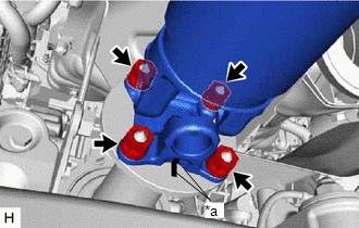
(a) Put matchmarks on the rear differential carrier assembly and propeller with center bearing shaft assembly. |
|
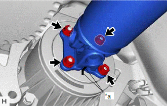
(b) Remove the 4 nuts and 4 washers.
(c) Using a brass bar and a hammer, separate the propeller with center bearing shaft assembly.
NOTICE:
Use wire or an equivalent tool to keep the propeller with center bearing shaft assembly.
|
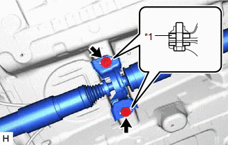
(d) Remove the 2 bolts and 2 center No. 2 support bearing washers (for rear side). NOTICE: When removing the bolts and center No. 2 support bearing washers, do not apply excessive force to the universal joint. |
|
|
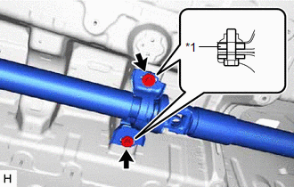
(e) Remove the 2 bolts and 2 center No. 2 support bearing washers (for front side). NOTICE: When removing the bolts and center No. 2 support bearing washers, do not apply excessive force to the universal joint. |
|
|
(f) Put matchmarks on the transfer assembly and propeller with center bearing shaft assembly. |
|
(g) Remove the 4 nuts, 4 washers and propeller with center bearing shaft assembly from the transfer assembly.
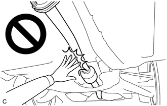
NOTICE:
- When removing the propeller with center bearing shaft assembly, do not apply excessive force to the universal joint.
- During and after the removal of the propeller with center bearing shaft assembly, keep the universal joint angle straight (within 15 degrees).
|
|
|