| Last Modified: 08-21-2023 | 6.11:8.1.0 | Doc ID: RM100000001PVCC |
| Model Year Start: 2021 | Model: Avalon | Prod Date Range: [08/2020 - ] |
| Title: A25A-FKS (FUEL): FUEL SENDER GAUGE ASSEMBLY: REMOVAL; 2021 - 2022 MY Avalon [08/2020 - ] | ||
REMOVAL
CAUTION / NOTICE / HINT
The necessary procedures (adjustment, calibration, initialization or registration) that must be performed after parts are removed and installed, or replaced during fuel sender gauge assembly or No. 2 fuel sender gauge assembly removal/installation are shown below.
Necessary Procedures After Parts Removed/Installed/Replaced
|
Replaced Part or Performed Procedure |
Necessary Procedure |
Effect/Inoperative Function when Necessary Procedure not Performed |
Link |
|---|---|---|---|
|
*1: When performing learning using the Techstream.
Click here
|
|||
|
Battery terminal is disconnected/reconnected |
Perform steering sensor zero point calibration |
Lane Departure Alert System (w/ Steering Control) |
|
|
Pre-collision System |
|||
|
Intelligent Clearance Sonar System*1 |
|||
|
Lighting System (for Gasoline Model with Cornering Light) |
|||
|
Memorize steering angle neutral point |
Parking Assist Monitor System |
|
|
|
Panoramic View Monitor System |
|
||
CAUTION:
-
Never perform work on fuel system components near any possible ignition sources.
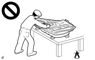
- Vaporized fuel could ignite, resulting in a serious accident.
-
Do not perform work on fuel system components without first disconnecting the cable from the negative (-) battery terminal.
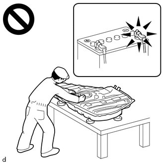
- Sparks could cause vaporized fuel to ignite, resulting in a serious accident.
NOTICE:
- After the engine switch is turned off, the radio and display receiver assembly records various types of memory and settings. As a result, after turning the engine switch off, make sure to wait at least 85 seconds before disconnecting the cable from the negative (-) battery terminal. (for Audio and Visual System)
- After the engine switch is turned off, the radio and display receiver assembly records various types of memory and settings. As a result, after turning the engine switch off, make sure to wait at least 85 seconds before disconnecting the cable from the negative (-) battery terminal. (for Navigation System)
PROCEDURE
1. REMOVE FUEL SUCTION TUBE WITH PUMP AND GAUGE ASSEMBLY
Click here
![2021 - 2022 MY Avalon [08/2020 - ]; A25A-FKS (FUEL): FUEL PUMP: REMOVAL](/t3Portal/stylegraphics/info.gif)
2. REMOVE FUEL SENDER GAUGE ASSEMBLY
|
(a) Disconnect the fuel sender gauge assembly connector. |
|
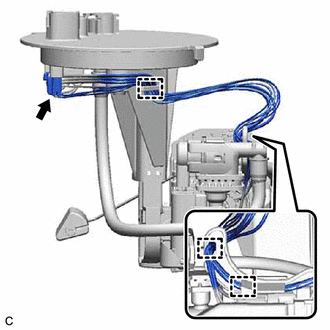
(b) Disengage the 3 clamps to disconnect the wire harness from the fuel suction tube with pump and gauge assembly.
NOTICE:
- Do not damage the wire harness.
- When disengaging each wire harness from the clamp, disengage one wire at a time.
|
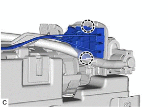
(c) Disengage the 2 claws to remove the fuel sender gauge assembly from the fuel suction tube with pump and gauge assembly. NOTICE: Be careful not to bend the arm of the fuel sender gauge assembly. |
|
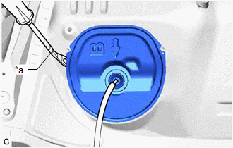
3. REMOVE REAR FLOOR SERVICE HOLE COVER
|
(a) Using a clip remover with its tip wrapped with protective tape, remove the rear floor service hole cover and butyl tape. |
|
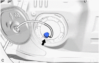
|
(b) Disconnect the fuel tank vent tube assembly connector. |
|
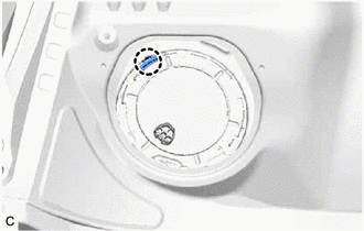
4. REMOVE FUEL PUMP GAUGE RETAINER
|
(a) Disengage the claw to remove the No. 1 fuel tube clamp. |
|
(b) Remove the fuel pump gauge retainer.
|
(1) Temporarily install SST (plate) and SST (claw) to the fuel pump gauge retainer. SST: 09808-01071 SST: 09808-14031 09808-01030 09808-01090 HINT: Securely insert the ends of SST (claw) into the insertion points in the fuel pump gauge retainer. |
|
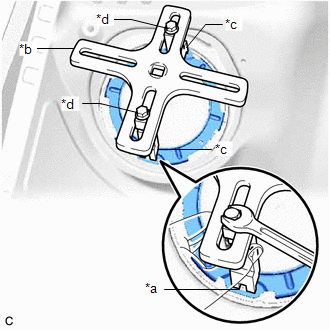
(2) While firmly pressing SST (claw) into the insertion points in the fuel pump gauge retainer, tighten SST (bolt).
|
(3) Install SST (handle) to SST (plate). SST: 09808-14031 09808-01010 |
|
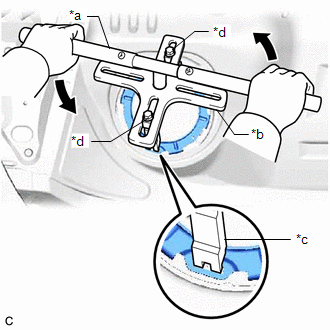
(4) Lightly press down on SST to prevent it from separating from the fuel pump gauge retainer. While pressing down on SST, rotate SST (handle) slowly to loosen the fuel pump gauge retainer.
NOTICE:
- Do not use any tools other than specified as this may result in damage to the fuel pump gauge retainer or fuel tank assembly.
- Do not press down on SST excessively as this may make the fuel pump gauge retainer hard to rotate, and may damage components.
- Make sure to rotate SST (handle) horizontally. If it is rotated at an angle, SST may come off.
- Do not spin SST too fast or use an impact wrench as this may result in damage to components.
- If SST comes off of the fuel pump gauge retainer, loosen SST (bolt) and reinstall SST.
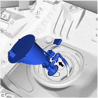
(5) While pressing down on the fuel tank vent tube assembly, remove the fuel pump gauge retainer.
5. REMOVE FUEL TANK VENT TUBE ASSEMBLY
|
(a) Raise the fuel tank vent tube assembly. NOTICE: Be careful not to bend the arm of the No. 2 fuel sender gauge assembly. |
|
(b) Disconnect the fuel return vent tube sub-assembly and remove the fuel tank vent tube assembly from the fuel tank assembly.
Click here
NOTICE:
When disconnecting the fuel tube connector, do not excessively pull on the fuel return vent tube sub-assembly.
|
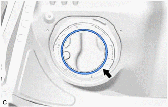
(c) Remove the fuel suction tube set gasket from the fuel tank assembly. |
|
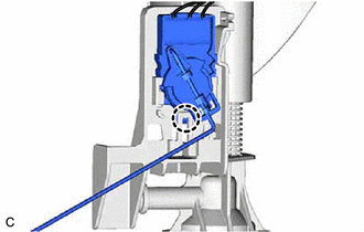
6. REMOVE NO. 2 FUEL SENDER GAUGE ASSEMBLY
|
(a) Disconnect the No. 2 fuel sender gauge assembly connector. |
|
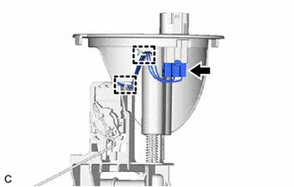
(b) Disengage the 2 clamps to disconnect the wire harness from the fuel tank vent tube assembly.
NOTICE:
- Do not damage the wire harness.
- When disengaging each wire harness from the clamp, disengage one wire at a time.
|
(c) Disengage the claw to remove the No. 2 fuel sender gauge assembly from the fuel tank vent tube assembly. NOTICE: Be careful not to bend the arm of the No. 2 fuel sender gauge assembly. |
|
|
|
|