| Last Modified: 08-21-2023 | 6.11:8.1.0 | Doc ID: RM100000001K5S1 |
| Model Year Start: 2020 | Model: Avalon | Prod Date Range: [08/2019 - 08/2020] |
| Title: AUDIO / VIDEO: AUDIO AND VISUAL SYSTEM (for Gasoline Model): Speaker Circuit; 2020 MY Avalon [08/2019 - 08/2020] | ||
|
Speaker Circuit |
DESCRIPTION
-
If there is a short in a speaker circuit, the radio and display receiver assembly detects it and stops output to the speakers.
Thus sound cannot be heard from the speakers even if there is no malfunction in the radio and display receiver assembly, DCM (telematics transceiver)* or speakers.
- *: w/ Manual (SOS) Switch
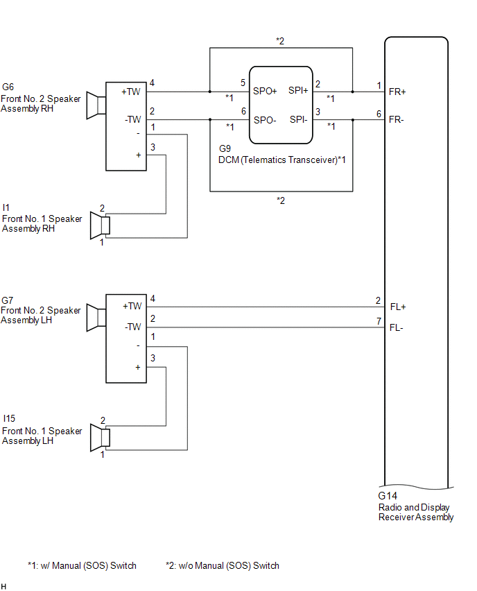
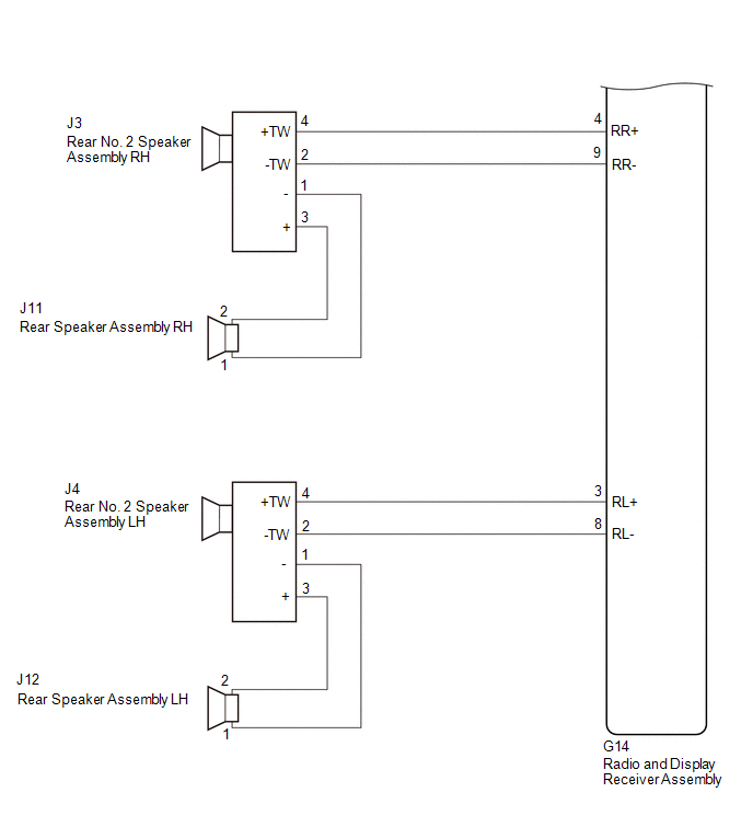
WIRING DIAGRAM
CAUTION / NOTICE / HINT
NOTICE:
-
Depending on the parts that are replaced during vehicle inspection or maintenance, performing initialization, registration or calibration may be needed. Refer to Precaution for Audio and Visual System.
Click here
![2019 - 2021 MY Avalon [04/2018 - 08/2021]; AUDIO / VIDEO: AUDIO AND VISUAL SYSTEM (for Gasoline Model): PRECAUTION](/t3Portal/stylegraphics/info.gif)
-
Before replacing the DCM (telematics transceiver), refer to Registration.
Click here
PROCEDURE
|
1. |
CHECK SPEAKER (OPERATION CHECK) |
|
(a) Enter the "System Check Mode" screen. Refer to Check Speaker in Operation Check. Click here
|
|
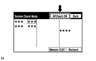
(b) Perform the operation check above and determine the speaker that is not operating.
|
Not Operating Speaker |
Proceed to |
|---|---|
|
Front No. 1 speaker assembly or front No. 2 speaker assembly (w/ Manual (SOS) Switch) |
A |
|
Front No. 1 speaker assembly or front No. 2 speaker assembly (w/o Manual (SOS) Switch) |
B |
|
Rear speaker assembly or rear No. 2 speaker assembly |
C |
HINT:
If sound cannot be heard from any speaker, inspect all of them.
| B |

|
| C |
|
|

|
2. |
CHECK HARNESS AND CONNECTOR (RADIO AND DISPLAY RECEIVER ASSEMBLY - FRONT NO. 1 SPEAKER ASSEMBLY - FRONT NO. 2 SPEAKER ASSEMBLY - DCM (TELEMATICS TRANSCEIVER)) |
(a) Disconnect the G14 radio and display receiver assembly connector.
(b) Disconnect the I1 and I15 front No. 1 speaker assembly connectors.
(c) Disconnect the G6 and G7 front No. 2 speaker assembly connectors.
(d) Disconnect the G9 DCM (telematics transceiver) connector.
(e) Measure the resistance according to the value (s) in the table below.
Standard Resistance:
|
Tester Connection |
Condition |
Specified Condition |
|---|---|---|
|
G14-1 (FR+) - G9-2 (SPI+) |
Always |
Below 1 Ω |
|
G14-6 (FR-) - G9-3 (SPI-) |
Always |
Below 1 Ω |
|
G9-5 (SPO+) - G6-4 (+TW) |
Always |
Below 1 Ω |
|
G9-6 (SPO-) - G6-2 (-TW) |
Always |
Below 1 Ω |
|
G14-2 (FL+) - G7-4 (+TW) |
Always |
Below 1 Ω |
|
G14-7 (FL-) - G7-2 (-TW) |
Always |
Below 1 Ω |
|
I1-2 - G6-3 (+) |
Always |
Below 1 Ω |
|
I1-1 - G6-1 (-) |
Always |
Below 1 Ω |
|
I15-2 - G7-3 (+) |
Always |
Below 1 Ω |
|
I15-1 - G7-1 (-) |
Always |
Below 1 Ω |
|
G14-1 (FR+) or G9-2 (SPI+) - Body ground |
Always |
10 kΩ or higher |
|
G14-6 (FR-) or G9-3 (SPI-) - Body ground |
Always |
10 kΩ or higher |
|
G9-5 (SPO+) or G6-4 (+TW) - Body ground |
Always |
10 kΩ or higher |
|
G9-6 (SPO-) or G6-2 (-TW) - Body ground |
Always |
10 kΩ or higher |
|
G14-2 (FL+) or G7-4 (+TW) - Body ground |
Always |
10 kΩ or higher |
|
G14-7 (FL-) or G7-2 (-TW) - Body ground |
Always |
10 kΩ or higher |
|
I1-2 or G6-3 (+) - Body ground |
Always |
10 kΩ or higher |
|
I1-1 or G6-1 (-) - Body ground |
Always |
10 kΩ or higher |
|
I15-2 or G7-3 (+) - Body ground |
Always |
10 kΩ or higher |
|
I15-1 or G7-1 (-) - Body ground |
Always |
10 kΩ or higher |
| NG |
|
REPAIR OR REPLACE HARNESS OR CONNECTOR |
|
|
3. |
INSPECT FRONT NO. 1 SPEAKER ASSEMBLY |
(a) Remove the front No. 1 speaker assembly.
Click here
(b) Inspect the front No. 1 speaker assembly.
Click here
| NG |
|
|
|
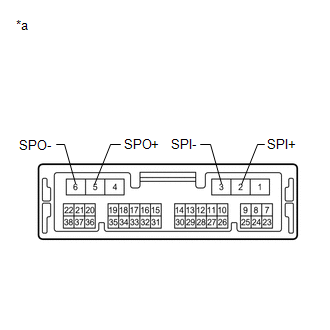
4. |
INSPECT DCM (TELEMATICS TRANSCEIVER) |
(a) Remove the DCM (telematics transceiver).
Click here
|
(b) Measure the resistance according to the value(s) in the table below. Standard Resistance:
|
|
| NG |
|
|
|
5. |
REPLACE FRONT NO. 2 SPEAKER ASSEMBLY |
(a) Remove the front No. 2 speaker assembly.
Click here
(b) Inspect the front No. 2 speaker assembly.
Click here
OK:
Malfunction disappears.
| OK |
|
END |
| NG |
|
PROCEED TO NEXT SUSPECTED AREA SHOWN IN PROBLEM SYMPTOMS TABLE |
|
6. |
CHECK HARNESS AND CONNECTOR (RADIO AND DISPLAY RECEIVER ASSEMBLY - FRONT NO. 1 SPEAKER ASSEMBLY - FRONT NO. 2 SPEAKER ASSEMBLY) |
(a) Disconnect the G14 radio and display receiver assembly connector.
(b) Disconnect the I1 and I15 front No. 1 speaker assembly connectors.
(c) Disconnect the G6 and G7 front No. 2 speaker assembly connectors.
(d) Measure the resistance according to the value (s) in the table below.
Standard Resistance:
|
Tester Connection |
Condition |
Specified Condition |
|---|---|---|
|
G14-1 (FR+) - G6-4 (+TW) |
Always |
Below 1 Ω |
|
G14-6 (FR-) - G6-2 (-TW) |
Always |
Below 1 Ω |
|
G14-2 (FL+) - G7-4 (+TW) |
Always |
Below 1 Ω |
|
G14-7 (FL-) - G7-2 (-TW) |
Always |
Below 1 Ω |
|
I1-2 - G6-3 (+) |
Always |
Below 1 Ω |
|
I1-1 - G6-1 (-) |
Always |
Below 1 Ω |
|
I15-2 - G7-3 (+) |
Always |
Below 1 Ω |
|
I15-1 - G7-1 (-) |
Always |
Below 1 Ω |
|
G14-1 (FR+) or G6-4 (+TW) - Body ground |
Always |
10 kΩ or higher |
|
G14-6 (FR-) or G6-2 (-TW) - Body ground |
Always |
10 kΩ or higher |
|
G14-2 (FL+) or G7-4 (+TW) - Body ground |
Always |
10 kΩ or higher |
|
G14-7 (FL-) or G7-2 (-TW) - Body ground |
Always |
10 kΩ or higher |
|
I1-2 or G6-3 (+) - Body ground |
Always |
10 kΩ or higher |
|
I1-1 or G6-1 (-) - Body ground |
Always |
10 kΩ or higher |
|
I15-2 or G7-3 (+) - Body ground |
Always |
10 kΩ or higher |
|
I15-1 or G7-1 (-) - Body ground |
Always |
10 kΩ or higher |
| NG |
|
REPAIR OR REPLACE HARNESS OR CONNECTOR |
|
|
7. |
INSPECT FRONT NO. 1 SPEAKER ASSEMBLY |
(a) Remove the front No. 1 speaker assembly.
Click here
(b) Inspect the front No. 1 speaker assembly.
Click here
| NG |
|
|
|
8. |
REPLACE FRONT NO. 2 SPEAKER ASSEMBLY |
(a) Remove the front No. 2 speaker assembly.
Click here
(b) Inspect the front No. 2 speaker assembly.
Click here
OK:
Malfunction disappears.
| OK |
|
END |
| NG |
|
PROCEED TO NEXT SUSPECTED AREA SHOWN IN PROBLEM SYMPTOMS TABLE |
|
9. |
CHECK HARNESS AND CONNECTOR (RADIO AND DISPLAY RECEIVER ASSEMBLY - REAR SPEAKER ASSEMBLY - REAR NO. 2 SPEAKER ASSEMBLY) |
(a) Disconnect the G14 radio and display receiver assembly connector.
(b) Disconnect the J11 and J12 rear speaker assembly connectors.
(c) Disconnect the J3 and J4 rear No. 2 speaker assembly connectors.
(d) Measure the resistance according to the value (s) in the table below.
Standard Resistance:
|
Tester Connection |
Condition |
Specified Condition |
|---|---|---|
|
G14-4 (RR+) - J3-4 (+TW) |
Always |
Below 1 Ω |
|
G14-9 (RR-) - J3-2 (-TW) |
Always |
Below 1 Ω |
|
G14-3 (RL+) - J4-4 (+TW) |
Always |
Below 1 Ω |
|
G14-8 (RL-) - J4-2 (-TW) |
Always |
Below 1 Ω |
|
J11-1 - J3-1 (-) |
Always |
Below 1 Ω |
|
J11-2 - J3-3 (+) |
Always |
Below 1 Ω |
|
J12-1 - J4-1 (-) |
Always |
Below 1 Ω |
|
J12-2 - J4-3 (+) |
Always |
Below 1 Ω |
|
G14-4 (RR+) or J3-4 (+TW) - Body ground |
Always |
10 kΩ or higher |
|
G14-9 (RR-) or J3-2 (-TW) - Body ground |
Always |
10 kΩ or higher |
|
G14-3 (RL+) or J4-4 (+TW) - Body ground |
Always |
10 kΩ or higher |
|
G14-8 (RL-) or J4-2 (-TW) - Body ground |
Always |
10 kΩ or higher |
|
J11-1 or J3-1 (-) - Body ground |
Always |
10 kΩ or higher |
|
J11-2 or J3-3 (+) - Body ground |
Always |
10 kΩ or higher |
|
J12-1 or J4-1 (-) - Body ground |
Always |
10 kΩ or higher |
|
J12-2 or J4-3 (+) - Body ground |
Always |
10 kΩ or higher |
| NG |
|
REPAIR OR REPLACE HARNESS OR CONNECTOR |
|
|
10. |
INSPECT REAR SPEAKER ASSEMBLY |
(a) Remove the rear speaker assembly.
Click here
(b) Inspect the rear speaker assembly.
Click here
| NG |
|
|
|
11. |
REPLACE REAR NO. 2 SPEAKER ASSEMBLY |
(a) Remove the rear No. 2 speaker assembly.
Click here
(b) Inspect the rear No. 2 speaker assembly.
Click here
OK:
Malfunction disappears.
| OK |
|
END |
| NG |
|
PROCEED TO NEXT SUSPECTED AREA SHOWN IN PROBLEM SYMPTOMS TABLE |
|
|
|