| Last Modified: 08-21-2023 | 6.11:8.1.0 | Doc ID: RM100000001JY8E |
| Model Year Start: 2020 | Model: Avalon | Prod Date Range: [08/2019 - 08/2021] |
| Title: PRE-COLLISION: PRE-COLLISION SYSTEM (for Gasoline Model): TERMINALS OF ECU; 2020 - 2021 MY Avalon [08/2019 - 08/2021] | ||
TERMINALS OF ECU

CHECK DRIVING SUPPORT ECU ASSEMBLY
(a) Measure the voltage and resistance according to the value(s) in the table below.
|
Terminal No. (Symbol) |
Wiring Color |
Terminal Description |
Condition |
Specified Condition |
|---|---|---|---|---|
|
G39-7 (B) - G39-28 (GND) |
B - W-B |
Power source |
Engine switch on (IG) |
11 to 14 V |
|
Engine switch off |
Below 1 V |
|||
|
G39-28 (GND) - Body ground |
W-B - Body ground |
Ground |
Always |
Below 1 Ω |
(b) Check for pulses according to the value(s) in the table below.
HINT:
If the waveform is not similar to that shown in the illustration, a malfunction of a CAN bus line, terminating resistor, or the driving support ECU assembly is suspected.
|
Terminal No. (Symbol) |
Wiring Color |
Terminal Description |
Condition |
Specified Condition |
|---|---|---|---|---|
|
G39-8 (CA1P) - G39-28 (GND) |
G - W-B |
CAN communication signal |
Engine switch on (IG) |
Pulse generation (See waveform 1) |
|
G39-9 (CA1N) - G39-28 (GND) |
W - W-B |
CAN communication signal |
Engine switch on (IG) |
Pulse generation (See waveform 2) |
|
G39-10 (CA2H) - G39-28 (GND) |
R - W-B |
CAN communication signal |
Engine switch on (IG) |
Pulse generation (See waveform 1) |
|
G39-11 (CA2L) - G39-28 (GND) |
W - W-B |
CAN communication signal |
Engine switch on (IG) |
Pulse generation (See waveform 2) |
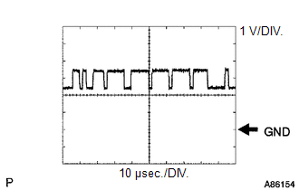
(1) WAVEFORM 1
|
Item |
Content |
|---|---|
|
Terminal Name |
Between G39-8 (CA1P) - G39-28 (GND) Between G39-10 (CA2H) - G39-28 (GND) |
|
Tester Range |
1 V/DIV., 10 μsec./DIV. |
|
Condition |
Engine switch on (IG) |
HINT:
The waveform varies depending on the CAN communication signal.
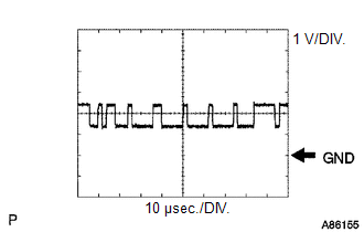
(2) WAVEFORM 2
|
Item |
Content |
|---|---|
|
Terminal Name |
Between G39-9 (CA1N) - G39-28 (GND) Between G39-11 (CA2L) - G39-28 (GND) |
|
Tester Range |
1 V/DIV., 10 μsec./DIV. |
|
Condition |
Engine switch on (IG) |
HINT:
The waveform varies depending on the CAN communication signal.

CHECK MILLIMETER WAVE RADAR SENSOR ASSEMBLY
(a) Measure the voltage and resistance according to the value(s) in the table below.
|
Terminal No. (Symbol) |
Wiring Color |
Terminal Description |
Condition |
Specified Condition |
|---|---|---|---|---|
|
A25-8 (IGB) - A25-1 (SGND) |
B - W-B |
Power source |
Engine switch on (IG) |
11 to 14 V |
|
A25-1 (SGND) - Body ground |
W-B - Body ground |
Ground |
Always |
Below 1 Ω |
(b) Check for pulses according to the value(s) in the table below.
HINT:
If the waveform is not similar to that shown in the illustration, a malfunction of a CAN bus line, terminating resistor, or the millimeter wave radar sensor assembly is suspected.
|
Terminal No. (Symbol) |
Wiring Color |
Terminal Description |
Condition |
Specified Condition |
|---|---|---|---|---|
|
A25-3 (CA2H) - A25-1 (SGND) |
R - W-B |
CAN communication signal |
Engine switch on (IG) |
Pulse generation (See waveform 1) |
|
A25-2 (CA2L) - A25-1 (SGND) |
W - W-B |
CAN communication signal |
Engine switch on (IG) |
Pulse generation (See waveform 2) |
|
A25-5 (CA1P) - A25-1 (SGND) |
G - W-B |
CAN communication signal |
Engine switch on (IG) |
Pulse generation (See waveform 1) |
|
A25-6 (CA1N) - A25-1 (SGND) |
W - W-B |
CAN communication signal |
Engine switch on (IG) |
Pulse generation (See waveform 2) |
(1) WAVEFORM 1
|
Item |
Content |
|---|---|
|
Terminal Name |
Between A25-3 (CA2H) and A25-1 (SGND) Between A25-5 (CA1P) and A25-1 (SGND) |
|
Tester Range |
1 V/DIV., 10 μsec./DIV. |
|
Condition |
Engine switch on (IG) |
HINT:
The waveform varies depending on the CAN communication signal.
(2) WAVEFORM 2
|
Item |
Content |
|---|---|
|
Terminal Name |
Between A25-2 (CA2L) and A25-1 (SGND) Between A25-6 (CA1N) and A25-1 (SGND) |
|
Tester Range |
1 V/DIV., 10 μsec./DIV. |
|
Condition |
Engine switch on (IG) |
HINT:
The waveform varies depending on the CAN communication signal.
|
|
|