| Last Modified: 09-10-2025 | 6.11:8.1.0 | Doc ID: RM100000001BYWE |
| Model Year Start: 2019 | Model: Avalon | Prod Date Range: [04/2018 - ] |
| Title: WIPER / WASHER: WIPER AND WASHER SYSTEM (for Gasoline Model): TERMINALS OF ECU; 2019 - 2022 MY Avalon [04/2018 - ] | ||
TERMINALS OF ECU
CHECK WINDSHIELD WIPER MOTOR ASSEMBLY

(a) Disconnect the A26 windshield wiper motor assembly connector.
(b) Measure the voltage and resistance on the wire harness side connector according to the value(s) in the table below.
|
Terminal No. (Symbol) |
Wiring Color |
Terminal Description |
Condition |
Specified Condition |
|---|---|---|---|---|
|
A26-1 (GND) - Body ground |
W-B - Body ground |
Ground |
Always |
Below 1 Ω |
|
A26-4 (+B) - Body ground |
SB - Body ground |
Engine switch on (IG) signal (Power source circuit) |
Engine switch on (IG) |
11 to 14 V |
|
Less than approximately 60 seconds after engine switch turned off |
||||
|
Approximately 60 seconds or more after engine switch turned off |
Below 1 V |
(c) Connect the A26 windshield wiper motor assembly connector.
HINT:
Since the A26 windshield wiper motor assembly connector is a waterproof type connector, the voltage and pulses cannot be checked directly. The values listed are for reference only.
(d) Measure the voltage and check for pulses according to the value(s) in the table below.
|
Terminal No. (Symbol) |
Wiring Color |
Terminal Description |
Condition |
Specified Condition |
|---|---|---|---|---|
|
A26-2 (LIN) - Body ground |
R - Body ground |
LIN communication signal |
Engine switch on (IG) |
Pulse generation |
|
A26-3 (2S) - Body ground |
B - Body ground |
Windshield wiper motor assembly HI operation signal |
Windshield wiper motor assembly stopped |
4.8 to 5.2 V |
|
Windshield wiper motor assembly operating in HI |
Below 1 V |
CHECK MAIN BODY ECU (MULTIPLEX NETWORK BODY ECU) AND INSTRUMENT PANEL JUNCTION BLOCK ASSEMBLY
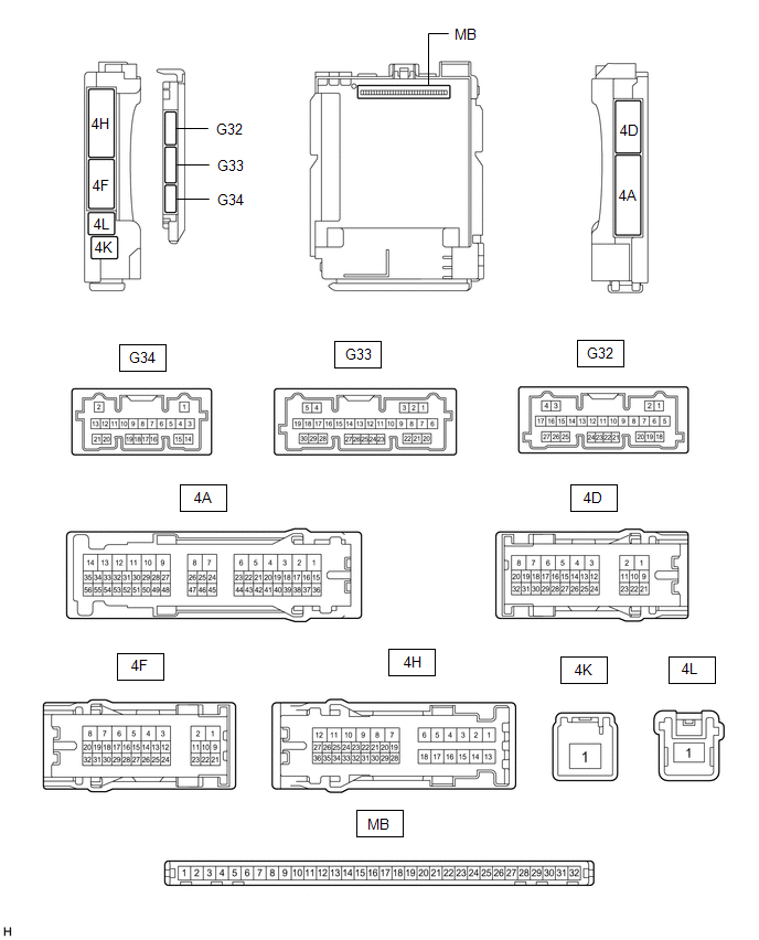
(a) Disconnect the instrument panel junction block assembly and main body ECU (multiplex network body ECU) connectors.
(b) Measure the voltage and resistance according to the value(s) in the table below.
|
Terminal No. (Symbol) |
Wiring Color |
Terminal Description |
Condition |
Specified Condition |
|---|---|---|---|---|
|
4D-3 - Body ground |
LA - Body ground |
Ground |
Always |
Below 1 Ω |
|
4F-1 - Body ground |
LG - Body ground |
Battery power supply |
Always |
11 to 14 V |
|
4K-1 - Body ground |
W - Body ground |
Battery power supply |
Always |
11 to 14 V |
(c) Connect the instrument panel junction block assembly and main body ECU (multiplex network body ECU) connectors.
(d) Measure the voltage and check for pulses according to the value(s) in the table below.
|
Terminal No. (Symbol) |
Wiring Color |
Terminal Description |
Condition |
Specified Condition |
|---|---|---|---|---|
|
4F-2 - Body ground |
R - Body ground |
Washer circuit IG power source |
Engine switch on (IG) |
11 to 14 V |
|
G32-3 (LIN3) - Body ground |
BE - Body ground |
LIN communication line |
Engine switch on (IG) |
Pulse generation |
|
G32-12 (FWSR) - Body ground |
L - Body ground |
WASHER Relay operation signal |
Engine switch on (IG), front washer switch off |
11 to 14 V |
|
Engine switch on (IG), front washer switch on |
Below 2 V |
|||
|
G33-21 (WPS) - Body ground |
LG - Body ground |
WIPER Relay operation signal |
Engine switch on (IG) |
11 to 14 V |
|
Less than approximately 60 seconds after engine switch turned off |
||||
|
Approximately 60 seconds or more after engine switch turned off |
Below 1 V |
CHECK COMBINATION METER ASSEMBLY
Click here
![2019 - 2020 MY Avalon [04/2018 - 08/2020]; METER / GAUGE / DISPLAY: METER / GAUGE SYSTEM (for Gasoline Model): TERMINALS OF ECU](/t3Portal/stylegraphics/info.gif)
|
|
|