| Last Modified: 09-10-2025 | 6.11:8.1.0 | Doc ID: RM100000001BYEL |
| Model Year Start: 2019 | Model: Avalon | Prod Date Range: [04/2018 - ] |
| Title: PARK ASSIST / MONITORING: INTUITIVE PARKING ASSIST SYSTEM (for Gasoline Model): No. 2 Clearance Warning Buzzer Circuit; 2019 - 2022 MY Avalon [04/2018 - ] | ||
|
No. 2 Clearance Warning Buzzer Circuit |
DESCRIPTION
This circuit consists of the No. 2 clearance warning buzzer and clearance warning ECU assembly. An ECU-excited type buzzer is used. The ECU operates the buzzers using a sound pattern that changes depending on the distance to the obstacle.
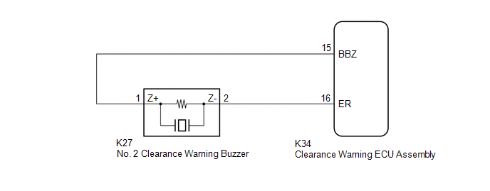
WIRING DIAGRAM
PROCEDURE
PROCEDURE
|
1. |
PERFORM ACTIVE TEST USING TECHSTREAM (REAR BUZZER) |
(a) Connect the Techstream to the DLC3.
(b) Turn the engine switch on (IG).
(c) Turn the Techstream on.
(d) Enter the following menus: Body Electrical / Advanced Parking Guidance/ICS/Intuitive P/A / Active Test.
(e) Check that the rear buzzer operates by performing the Active Test.
Body Electrical > Advanced Parking Guidance/ICS/Intuitive P/A > Active Test
|
Tester Display |
Measurement Item |
Control Range |
Diagnostic Note |
|---|---|---|---|
|
Rear Buzzer |
No. 2 clearance warning buzzer |
Stop or Operate |
Confirm that the vehicle is stopped and the engine switch is on (IG) |
Body Electrical > Advanced Parking Guidance/ICS/Intuitive P/A > Active Test
|
Tester Display |
|---|
|
Rear Buzzer |
OK:
The No. 2 clearance warning buzzer sounds.
| OK |

|
PROCEED TO NEXT SUSPECTED AREA SHOWN IN PROBLEM SYMPTOMS TABLE |
| NG |
|
|
2. |
CHECK HARNESS AND CONNECTOR (CLEARANCE WARNING ECU ASSEMBLY - NO. 2 CLEARANCE WARNING BUZZER) |
(a) Disconnect the K34 clearance warning ECU assembly connector.
(b) Disconnect the K27 No. 2 clearance warning buzzer connector.
(c) Measure the resistance according to the value(s) in the table below.
Standard Resistance:
|
Tester Connection |
Condition |
Specified Condition |
|---|---|---|
|
K34-15 (BBZ) - K27-1 (Z+) |
Always |
Below 1 Ω |
|
K34-16 (ER) - K27-2 (Z-) |
Always |
Below 1 Ω |
|
K34-15 (BBZ) or K27-1 (Z+) - Body ground |
Always |
10 kΩ or higher |
|
K34-16 (ER) or K27-2 (Z-) - Body ground |
Always |
10 kΩ or higher |
| NG |
|
REPAIR OR REPLACE HARNESS OR CONNECTOR |
|

|
3. |
REPLACE NO. 2 CLEARANCE WARNING BUZZER |
(a) Replace the No. 2 clearance warning buzzer with a new or known good one.
Click here
![2019 - 2020 MY Avalon HV Avalon [04/2018 - 08/2020]; PARK ASSIST / MONITORING: CLEARANCE WARNING BUZZER (for Rear): REMOVAL](/t3Portal/stylegraphics/info.gif)
|
|
4. |
PERFORM ACTIVE TEST USING TECHSTREAM (REAR BUZZER) |
(a) Connect the Techstream to the DLC3.
(b) Turn the engine switch on (IG).
(c) Turn the Techstream on.
(d) Enter the following menus: Body Electrical / Advanced Parking Guidance/ICS/Intuitive P/A / Active Test.
(e) Check that the rear buzzer operates by performing the Active Test.
Body Electrical > Advanced Parking Guidance/ICS/Intuitive P/A > Active Test
|
Tester Display |
Measurement Item |
Control Range |
Diagnostic Note |
|---|---|---|---|
|
Rear Buzzer |
No. 2 clearance warning buzzer |
Stop or Operate |
Confirm that the vehicle is stopped and the engine switch is on (IG) |
Body Electrical > Advanced Parking Guidance/ICS/Intuitive P/A > Active Test
|
Tester Display |
|---|
|
Rear Buzzer |
OK:
The No. 2 clearance warning buzzer sounds.
| OK |
|
END (NO. 2 CLEARANCE WARNING BUZZER WAS DEFECTIVE) |
| NG |
|
REPLACE CLEARANCE WARNING ECU ASSEMBLY Click here
|
|
|
|