| Last Modified: 08-21-2023 | 6.11:8.1.0 | Doc ID: RM100000001BTD1 |
| Model Year Start: 2019 | Model: Avalon HV | Prod Date Range: [04/2018 - ] |
| Title: NAVIGATION / MULTI INFO DISPLAY: NAVIGATION SYSTEM (for HV Model): Reverse Signal Circuit between Radio Receiver Assembly and Navigation ECU; 2019 - 2022 MY Avalon HV [04/2018 - ] | ||
|
Reverse Signal Circuit between Radio Receiver Assembly and Navigation ECU |
DESCRIPTION
This circuit includes the navigation ECU and radio and display receiver assembly.
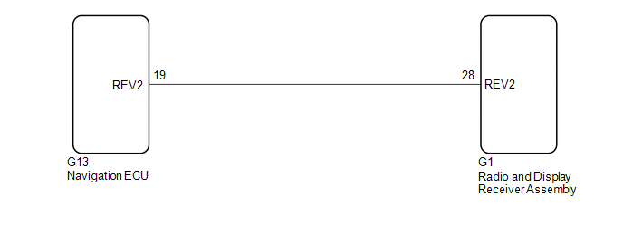
WIRING DIAGRAM
PROCEDURE
|
1. |
CHECK HARNESS AND CONNECTOR (RADIO AND DISPLAY RECEIVER ASSEMBLY - NAVIGATION ECU) |
(a) Disconnect the G1 radio and display receiver assembly connector.
(b) Disconnect the G13 navigation ECU connector.
(c) Measure the resistance according to the value(s) in the table below.
Standard Resistance:
|
Tester Connection |
Condition |
Specified Condition |
|---|---|---|
|
G1-28 (REV2) - G13-19 (REV2) |
Always |
Below 1 Ω |
|
G1-28 (REV2) or G13-19 (REV2) - Body ground |
Always |
10 kΩ or higher |
| OK |

|
PROCEED TO NEXT SUSPECTED AREA SHOWN IN PROBLEM SYMPTOMS TABLE
|
![2019 - 2020 MY Avalon HV [04/2018 - 08/2020]; NAVIGATION / MULTI INFO DISPLAY: NAVIGATION SYSTEM (for HV Model): PROBLEM SYMPTOMS TABLE](/t3Portal/stylegraphics/info.gif)
| NG |
|
REPAIR OR REPLACE HARNESS OR CONNECTOR |
|
|
|