| 
                     
                        | Last Modified: 08-21-2023 | 6.11:8.1.0 | Doc ID: RM100000001BTBG |  
                        | Model Year Start: 2019 | Model: Avalon HV | Prod Date Range: [04/2018 - 08/2019] |  
                        | Title: NAVIGATION / MULTI INFO DISPLAY: NAVIGATION SYSTEM (for HV Model): B15C3; Speaker Output Short; 2019 MY Avalon HV [04/2018 - 08/2019] |  
                     
                        
                           | DTC | B15C3 | Speaker Output Short |  DESCRIPTIONThis DTC is stored when a malfunction occurs in the speakers. 


                           | DTC No. | Detection Item | DTC Detection Condition | Trouble Area |  
                           | B15C3 | Speaker Output Short | A short is detected in the speaker output circuit | 
                                 
                                    
Harness or connector
Speaker
DCM (telematics transceiver)
Stereo Component Amplifier
 |  WIRING DIAGRAM        CAUTION / NOTICE / HINT
                     NOTICE: 
                        
Depending on the parts that are replaced during vehicle inspection or maintenance, performing initialization, registration or calibration may be needed. Refer to Precaution for Navigation System.
Click here
                                 
                                    
                                       ![2019 - 2021 MY Avalon HV [04/2018 - 08/2021]; NAVIGATION / MULTI INFO DISPLAY: NAVIGATION SYSTEM (for HV Model): PRECAUTION](/t3Portal/stylegraphics/info.gif) 
When replacing the radio and display receiver assembly, always replace it with a new one. If a radio and display receiver assembly which was installed to another vehicle is used, the following may occur:
                              
                                 
A communication malfunction DTC may be stored.
The radio and display receiver assembly may not operate normally.
Before replacing the DCM (telematics transceiver), refer to Registration.
Click here
                                 
                                    
                                       ![2019 - 2020 MY Avalon HV [04/2018 - 08/2020]; THEFT DETERRENT / KEYLESS ENTRY: SMART KEY SYSTEM (for Start Function, HV Model): REGISTRATION](/t3Portal/stylegraphics/info.gif)  PROCEDURE
                     
                        
                           | 1.  | CHECK HARNESS AND CONNECTOR (STEREO COMPONENT AMPLIFIER ASSEMBLY, DCM (TELEMATICS TRANSCEIVER) OR SPEAKERS - BODY GROUND) |  
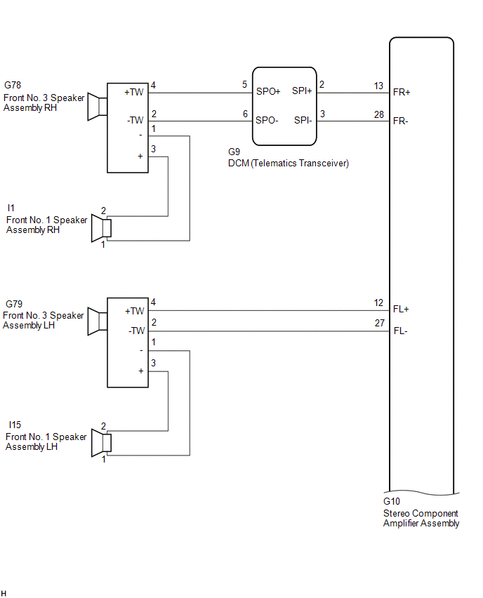
(a) Disconnect the G10 stereo component amplifier assembly connector. (b) Disconnect the G9 DCM (telematics transceiver) connector. 
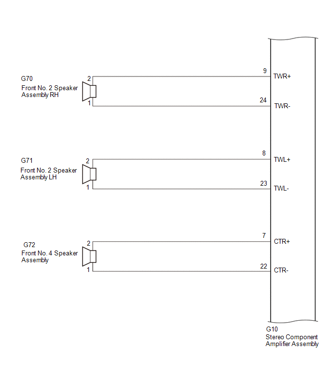
(c) Disconnect the G70 and G71 front No. 2 speaker assembly connectors. (d) Disconnect the G72 front No. 4 speaker assembly connector. (e) Disconnect the G79 front No. 3 speaker assembly LH connector. 
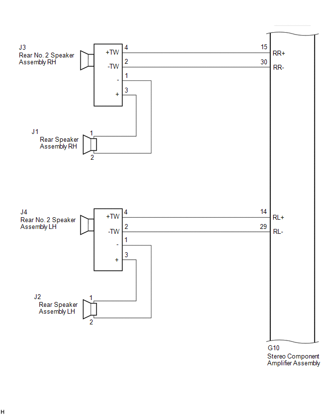
(f) Disconnect the J3 and J4 rear No. 2 speaker assembly connectors. 
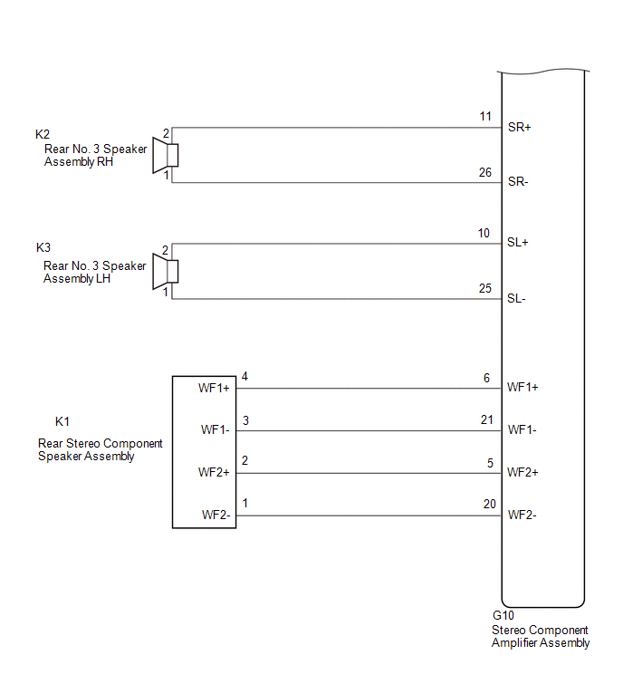
(g) Disconnect the K2 and K3 speaker assembly with bracket connectors. (h) Disconnect the K1 rear No. 3 speaker assembly connector. (i) Measure the resistance according to the value(s) in the table below. Standard Resistance:  


                           | Tester Connection | Condition | Specified Condition |  
                           | G10-9 (TWR+) or G70-2 - Body ground | Always | 10 kΩ or higher |  
                           | G10-24 (TWR-) or G70-1 - Body ground | Always | 10 kΩ or higher |  
                           | G10-8 (TWL+) or G71-2 - Body ground | Always | 10 kΩ or higher |  
                           | G10-23 (TWL-) or G71-1 - Body ground | Always | 10 kΩ or higher |  
                           | G10-13 (FR+) or G9-2 (SPI+) - Body ground | Always | 10 kΩ or higher |  
                           | G10-28 (FR-) or G9-3 (SPI-) - Body ground | Always | 10 kΩ or higher |  
                           | G10-12 (FL+) or G79-4 (+TW) - Body ground | Always | 10 kΩ or higher |  
                           | G10-27 (FL-) or G79-2 (-TW) - Body ground | Always | 10 kΩ or higher |  
                           | G10-15 (RR+) or J3-4 (+TW) - Body ground | Always | 10 kΩ or higher |  
                           | G10-30 (RR-) or J3-2 (-TW) - Body ground | Always | 10 kΩ or higher |  
                           | G10-14 (RL+) or J4-4 (+TW) - Body ground | Always | 10 kΩ or higher |  
                           | G10-29 (RL-) or J4-2 (-TW) - Body ground | Always | 10 kΩ or higher |  
                           | G10-6 (WF1+) or K1-4 (WF1+) - Body ground | Always | 10 kΩ or higher |  
                           | G10-21 (WF1-) or K1-3 (WF1-) - Body ground | Always | 10 kΩ or higher |  
                           | G10-5 (WF2+) or K1-2 (WF2+) - Body ground | Always | 10 kΩ or higher |  
                           | G10-20 (WF2-) or K1-1 (WF2-) - Body ground | Always | 10 kΩ or higher |  
                           | G10-7 (CTR+) or G72-2 - Body ground | Always | 10 kΩ or higher |  
                           | G10-22 (CTR-) or G72-1 - Body ground | Always | 10 kΩ or higher |  
                           | G10-11 (SR+) or K2-2 - Body ground | Always | 10 kΩ or higher |  
                           | G10-26 (SR-) or K2-1 - Body ground | Always | 10 kΩ or higher |  
                           | G10-10 (SL+) or K3-2 - Body ground | Always | 10 kΩ or higher |  
                           | G10-25 (SL-) or K3-1 - Body ground | Always | 10 kΩ or higher |  
                     
                        
                           | NG |   | REPAIR OR REPLACE HARNESS OR CONNECTOR |  
                     
                        | 
                              
                                 | OK |  
                                 |   |  |  
                     
                        
                           | 2.  | CHECK HARNESS AND CONNECTOR (DCM (TELEMATICS TRANSCEIVER) OR SPEAKER - BODY GROUND) |  (a) Disconnect the G9 DCM (telematics transceiver) connector. (b) Disconnect the G78 front No. 3 speaker assembly RH connector. (c) Measure the resistance according to the value(s) in the table below. Standard Resistance:  


                           | Tester Connection | Condition | Specified Condition |  
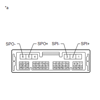
                           | G9-5 (SPO+) or G78-4 (+TW) - Body ground | Always | 10 kΩ or higher |  
                           | G9-6 (SPO-) or G78-2 (-TW) - Body ground | Always | 10 kΩ or higher |  
                     
                        
                           | NG |   | REPAIR OR REPLACE HARNESS OR CONNECTOR |  
                     
                        | 
                              
                                 | OK |  
                                 |   |  |  
                     
                        
                           | 3.  | INSPECT DCM (TELEMATICS TRANSCEIVER) |  (a) Remove the DCM (telematics transceiver). Click here
                        
                           
                              ![2019 - 2020 MY Avalon Avalon HV [04/2018 - 08/2020]; CELLULAR COMMUNICATION: DCM(TELEMATICS TRANSCEIVER): REMOVAL](/t3Portal/stylegraphics/info.gif)  
                     
                        
                           | (b) Measure the resistance according to the value(s) in the table below. Standard Resistance:  


                                       | Tester Connection | Condition | Specified Condition |  
                                       | 2 (SPI+) - 5 (SPO+) | Always | Below 1 Ω |  
                                       | 3 (SPI-) - 6 (SPO-) | Always | Below 1 Ω |  
                                       | 2 (SPI+) - 3 (SPI-) | Always | 10 kΩ or higher |  
                                       | 5 (SPO+) - 6 (SPO-) | Always | 10 kΩ or higher |  
                                       | 2 (SPI+) or 5 (SPO+) - Body ground | Always | 10 kΩ or higher |  
                                       | 3 (SPI-) or 6 (SPO-) - Body ground | Always | 10 kΩ or higher |  | 
                                 
                                    |   |  
                                    | 


                                                | *a | Component without harness connected (DCM (Telematics Transceiver)) |  |  |  
                     
                        | 
                              
                                 | OK |  
                                 |   |  |  
                     
                        
                           | 4.  | CHECK HARNESS AND CONNECTOR (FRONT NO. 1 SPEAKER ASSEMBLY OR FRONT NO. 3 SPEAKER ASSEMBLY - BODY GROUND) |  (a) Disconnect the I1 and I15 front No. 1 speaker assembly connectors. (b) Disconnect the G78 and G79 front No. 3 speaker assembly connectors. (c) Measure the resistance according to the value(s) in the table below. Standard Resistance:  


                           | Tester Connection | Condition | Specified Condition |  
                           | I1-2 or G78-3 (+) - Body ground | Always | 10 kΩ or higher |  
                           | I1-1 or G78-1 (-) - Body ground | Always | 10 kΩ or higher |  
                           | I15-2 or G79-3 (+) - Body ground | Always | 10 kΩ or higher |  
                           | I15-1 or G79-1 (-) - Body ground | Always | 10 kΩ or higher |  
                     
                        
                           | NG |   | REPAIR OR REPLACE HARNESS OR CONNECTOR |  
                     
                        | 
                              
                                 | OK |  
                                 |   |  |  
                     
                        
                           | 5.  | CHECK HARNESS AND CONNECTOR (REAR SPEAKER ASSEMBLY OR REAR NO. 2 SPEAKER ASSEMBLY - BODY GROUND) |  (a) Disconnect the J3 and J4 rear No. 2 speaker assembly connectors. (b) Disconnect the J1 and J2 rear speaker assembly connectors. (c) Measure the resistance according to the value(s) in the table below. Standard Resistance:  


                           | Tester Connection | Condition | Specified Condition |  
                           | J1-1 or J3-3 (+) - Body ground | Always | 10 kΩ or higher |  
                           | J1-2 or J3-1 (-) - Body ground | Always | 10 kΩ or higher |  
                           | J2-1 or J4-3 (+) - Body ground | Always | 10 kΩ or higher |  
                           | J2-2 or J4-1 (-) - Body ground | Always | 10 kΩ or higher |  
                     
                        
                           | NG |   | REPAIR OR REPLACE HARNESS OR CONNECTOR |  
                     
                        | 
                              
                                 | OK |  
                                 |   |  |  
                     
                        
                           | 6.  | INSPECT FRONT NO. 1 SPEAKER ASSEMBLY |  (a) Remove the front No. 1 speaker assembly. Click here
                        
                           
                              ![2019 - 2022 MY Avalon Avalon HV [04/2018 -        ]; AUDIO / VIDEO: FRONT DOOR SPEAKER: REMOVAL](/t3Portal/stylegraphics/info.gif)  (b) Inspect the front No. 1 speaker assembly. Click here
                        
                           
                              ![2019 - 2022 MY Avalon Avalon HV [04/2018 -        ]; AUDIO / VIDEO: FRONT DOOR SPEAKER: INSPECTION](/t3Portal/stylegraphics/info.gif)  
                     
                        | 
                              
                                 | OK |  
                                 |   |  |  
                     
                        
                           | 7.  | INSPECT FRONT NO. 2 SPEAKER ASSEMBLY |  (a) Remove the front No. 2 speaker assembly. Click here
                        
                           
                              ![2019 - 2022 MY Avalon Avalon HV [04/2018 -        ]; AUDIO / VIDEO: INSTRUMENT PANEL SPEAKER: REMOVAL](/t3Portal/stylegraphics/info.gif)  (b) Inspect the front No. 2 speaker assembly. Click here
                        
                           
                              ![2019 - 2022 MY Avalon Avalon HV [04/2018 -        ]; AUDIO / VIDEO: INSTRUMENT PANEL SPEAKER: INSPECTION](/t3Portal/stylegraphics/info.gif)  
                     
                        | 
                              
                                 | OK |  
                                 |   |  |  
                     
                        
                           | 8.  | INSPECT FRONT NO. 4 SPEAKER ASSEMBLY |  (a) Remove the front No. 4 speaker assembly. Click here
                        
                           
                              ![2019 - 2022 MY Avalon Avalon HV [04/2018 -        ]; AUDIO / VIDEO: INSTRUMENT PANEL SPEAKER: REMOVAL](/t3Portal/stylegraphics/info.gif)  (b) Inspect the front No. 4 speaker assembly. Click here
                        
                           
                              ![2019 - 2022 MY Avalon Avalon HV [04/2018 -        ]; AUDIO / VIDEO: INSTRUMENT PANEL SPEAKER: INSPECTION](/t3Portal/stylegraphics/info.gif)  
                     
                        | 
                              
                                 | OK |  
                                 |   |  |  
                     
                        
                           | 9.  | INSPECT REAR SPEAKER ASSEMBLY |  (a) Remove the rear speaker assembly. Click here
                        
                           
                              ![2019 - 2022 MY Avalon Avalon HV [04/2018 -        ]; AUDIO / VIDEO: REAR DOOR SPEAKER: REMOVAL](/t3Portal/stylegraphics/info.gif)  (b) Inspect the rear speaker assembly. Click here
                        
                           
                              ![2019 MY Avalon Avalon HV [04/2018 - 08/2019]; AUDIO / VIDEO: REAR DOOR SPEAKER: INSPECTION](/t3Portal/stylegraphics/info.gif)  
                     
                        | 
                              
                                 | OK |  
                                 |   |  |  
                     
                        
                           | 10.  | INSPECT REAR NO. 3 SPEAKER ASSEMBLY |  (a) Remove the rear No. 3 speaker assembly. Click here
                        
                           
                              ![2019 - 2021 MY Avalon Avalon HV [04/2018 - 08/2021]; AUDIO / VIDEO: REAR PACKAGE TRAY SPEAKER: REMOVAL](/t3Portal/stylegraphics/info.gif)  (b) Inspect the rear No. 3 speaker assembly. Click here
                        
                           
                              ![2019 - 2022 MY Avalon Avalon HV [04/2018 -        ]; AUDIO / VIDEO: REAR PACKAGE TRAY SPEAKER: INSPECTION](/t3Portal/stylegraphics/info.gif)  
                     
                        | 
                              
                                 | OK |  
                                 |   |  |  
                     
                        
                           | 11.  | INSPECT SPEAKER ASSEMBLY WITH BRACKET |  (a) Remove the speaker assembly with bracket. Click here
                        
                           
                              ![2019 - 2021 MY Avalon Avalon HV [04/2018 - 08/2021]; AUDIO / VIDEO: REAR PACKAGE TRAY SPEAKER: REMOVAL](/t3Portal/stylegraphics/info.gif)  (b) Inspect the speaker assembly with bracket. Click here
                        
                           
                              ![2019 - 2022 MY Avalon Avalon HV [04/2018 -        ]; AUDIO / VIDEO: REAR PACKAGE TRAY SPEAKER: INSPECTION](/t3Portal/stylegraphics/info.gif)  
                     
                        | 
                              
                                 | OK |  
                                 |   |  |  
                     
                        
                           | 12.  | REPLACE FRONT NO. 3 SPEAKER ASSEMBLY |  (a) Remove the front No. 3 speaker assembly. Click here
                        
                           
                              ![2019 - 2022 MY Avalon Avalon HV [04/2018 -        ]; AUDIO / VIDEO: PILLAR SPEAKER: REMOVAL](/t3Portal/stylegraphics/info.gif)  (b) Inspect the front No. 3 speaker assembly. Click here
                        
                           
                              ![2019 - 2022 MY Avalon Avalon HV [04/2018 -        ]; AUDIO / VIDEO: PILLAR SPEAKER: INSPECTION](/t3Portal/stylegraphics/info.gif)  (c) Clear the DTCs. Body Electrical > Navigation System > Clear DTCs(d) Recheck for DTCs and check that no DTCs are output. Body Electrical > Navigation System > Trouble CodesOK:  No DTCs are output. 
                     
                        
                           | OK |   | END |  
                     
                        | 
                              
                                 | NG |  
                                 |   |  |  
                     
                        
                           | 13.  | REPLACE REAR NO. 2 SPEAKER ASSEMBLY |  (a) Remove the rear No. 2 speaker assembly. Click here
                        
                           
                              ![2019 - 2022 MY Avalon Avalon HV [04/2018 -        ]; AUDIO / VIDEO: REAR DOOR SPEAKER: REMOVAL](/t3Portal/stylegraphics/info.gif)  (b) Inspect the rear No. 2 speaker assembly. Click here
                        
                           
                              ![2019 MY Avalon Avalon HV [04/2018 - 08/2019]; AUDIO / VIDEO: REAR DOOR SPEAKER: INSPECTION](/t3Portal/stylegraphics/info.gif)  (c) Clear the DTCs. Body Electrical > Navigation System > Clear DTCs(d) Recheck for DTCs and check that no DTCs are output. Body Electrical > Navigation System > Trouble CodesOK:  No DTCs are output. 
                     
                        
                           | OK |   | END |  |