| Last Modified: 09-10-2025 | 6.11:8.1.0 | Doc ID: RM100000001BTBB |
| Model Year Start: 2019 | Model: Avalon HV | Prod Date Range: [04/2018 - ] |
| Title: NAVIGATION / MULTI INFO DISPLAY: NAVIGATION SYSTEM (for HV Model): B158F; AV Signal Stoppage (Low Battery Voltage); 2019 - 2022 MY Avalon HV [04/2018 - ] | ||
|
DTC |
B158F |
AV Signal Stoppage (Low Battery Voltage) |
DESCRIPTION
This DTC is stored when a video or audio signal is interrupted due to auxiliary battery voltage input to the radio and display receiver assembly dropping temporarily.
|
DTC No. |
Detection Item |
DTC Detection Condition |
Trouble Area |
|---|---|---|---|
|
B158F |
AV Signal Stoppage (Low Battery Voltage) |
A video or audio signal is interrupted when the auxiliary battery voltage drops |
|
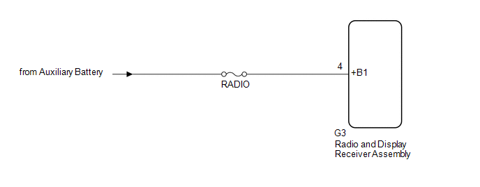
WIRING DIAGRAM
CAUTION / NOTICE / HINT
NOTICE:
-
Depending on the parts that are replaced during vehicle inspection or maintenance, performing initialization, registration or calibration may be needed. Refer to Precaution for Navigation System.
Click here
![2019 - 2021 MY Avalon HV [04/2018 - 08/2021]; NAVIGATION / MULTI INFO DISPLAY: NAVIGATION SYSTEM (for HV Model): PRECAUTION](/t3Portal/stylegraphics/info.gif)
-
When replacing the radio and display receiver assembly, always replace it with a new one. If a radio and display receiver assembly which was installed to another vehicle is used, the following may occur:
- A communication malfunction DTC may be stored.
- The radio and display receiver assembly may not operate normally.
- Inspect the fuses for circuits related to this system before performing the following procedure.
PROCEDURE
PROCEDURE
|
1. |
CHECK VEHICLE SIGNAL (OPERATION CHECK) |
|
(a) Enter the "Vehicle Signal Check Mode" screen. Refer to Check Vehicle Signal in Operation Check. Click here
|
|
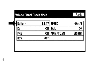
(b) Measure the auxiliary battery voltage.
Standard Voltage:
11 to 15.5 V
HINT:
This display is updated once per second.
| NG |

|
|

|
2. |
CHECK DTC |
(a) Clear the DTCs.
Body Electrical > Navigation System > Clear DTCs
(b) Recheck for DTCs and check that no DTCs are output.
Body Electrical > Navigation System > Trouble Codes
OK:
No DTCs are output.
| OK |
|
END |
| NG |
|
|
3. |
CHECK HARNESS AND CONNECTOR (RADIO AND DISPLAY RECEIVER ASSEMBLY POWER SOURCE) |
(a) Disconnect the G3 radio and display receiver assembly connector.
(b) Measure the voltage according to the value(s) in the table below.
Standard Voltage:
|
Tester Connection |
Condition |
Specified Condition |
|---|---|---|
|
G3-4 (+B1) - Body ground |
Power switch off |
11 to 14 V |
| OK |
|
| NG |
|
REPAIR OR REPLACE HARNESS OR CONNECTOR |
|
|
|