| Last Modified: 09-10-2025 | 6.11:8.1.0 | Doc ID: RM100000001BQPQ |
| Model Year Start: 2019 | Model: Avalon HV | Prod Date Range: [04/2018 - ] |
| Title: THEFT DETERRENT / KEYLESS ENTRY: THEFT DETERRENT SYSTEM (for HV Model): Power Source Circuit; 2019 - 2022 MY Avalon HV [04/2018 - ] | ||
|
Power Source Circuit |
DESCRIPTION
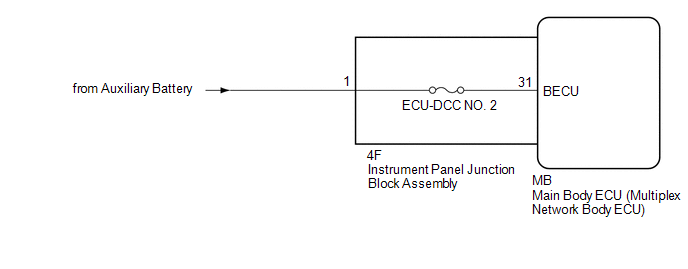
Based on changes in the power source voltage, the main body ECU (multiplex network body ECU) can detect if the auxiliary battery has been disconnected and reconnected.
WIRING DIAGRAM
CAUTION / NOTICE / HINT
NOTICE:
-
Before replacing the main body ECU (multiplex network body ECU), refer to Registration.
Click here
![2019 - 2020 MY Avalon HV [04/2018 - 08/2020]; THEFT DETERRENT / KEYLESS ENTRY: SMART KEY SYSTEM (for Start Function, HV Model): REGISTRATION](/t3Portal/stylegraphics/info.gif)
- Inspect the fuses for circuits related to this system before performing the following procedure.
PROCEDURE
PROCEDURE
|
1. |
CHECK HARNESS AND CONNECTOR (POWER SUPPLY) |
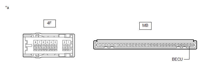
(a) Disconnect the 4F instrument panel junction block assembly connector.
(b) Measure the voltage according to the value(s) in the table below.
Standard Voltage:
|
Tester Connection |
Condition |
Specified Condition |
|---|---|---|
|
4F-1 - Body ground |
Always |
8.5 V or higher |
| NG |

|
REPAIR OR REPLACE HARNESS OR CONNECTOR |
|

|
2. |
INSPECT INSTRUMENT PANEL JUNCTION BLOCK ASSEMBLY |
(a) Remove the main body ECU (multiplex network body ECU).
Click here
|
*a |
Component without harness connected (Instrument Panel Junction Block Assembly) |
- |
- |
(b) Measure the resistance according to the value(s) in the table below.
Standard Resistance:
|
Tester Connection |
Condition |
Specified Condition |
|---|---|---|
|
4F-1 - MB-31 (BECU) |
Always |
Below 1 Ω |
| OK |
|
REPLACE MAIN BODY ECU (MULTIPLEX NETWORK BODY ECU) Click here
|
| NG |
|
REPLACE INSTRUMENT PANEL JUNCTION BLOCK ASSEMBLY Click here
|
|
|
|