| Last Modified: 09-10-2025 | 6.11:8.1.0 | Doc ID: RM100000001BF9Q |
| Model Year Start: 2019 | Model: Avalon | Prod Date Range: [04/2018 - 08/2020] |
| Title: CELLULAR COMMUNICATION: SAFETY CONNECT SYSTEM (for Gasoline Model): B15C0,B15C1; Short in GPS Antenna; 2019 - 2020 MY Avalon [04/2018 - 08/2020] | ||
|
DTC |
B15C0 |
Short in GPS Antenna |
|
DTC |
B15C1 |
Open in GPS Antenna |
DESCRIPTION
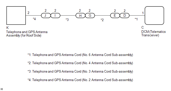
These DTCs are stored when the DCM (Telematics Transceiver) detects an open or a short in the telephone and GPS antenna assembly (for Roof Side) circuit. The DCM (Telematics Transceiver) receives 1574.42 - 1576.42 MHz radio frequency signals from satellites through the telephone and GPS antenna assembly (for Roof Side). The cable is a 50 Ω coaxial cable.
|
DTC No. |
Detection Item |
DTC Detection Condition |
Trouble Area |
|---|---|---|---|
|
B15C0 |
Short in GPS Antenna |
Current for telephone and GPS antenna assembly (for Roof Side) is lower (Ω) malfunction criterion for 10 seconds when engine switch is on (IG). (Short circuit) |
|
|
B15C1 |
Open in GPS Antenna |
Current for telephone and GPS antenna assembly (for Roof Side) is higher (Ω) malfunction criterion for 10 seconds when engine switch is on (IG). (Open circuit) |
|
WIRING DIAGRAM
CAUTION / NOTICE / HINT
HINT:
-
Before performing this diagnostic procedure, make sure to perform Health Check and confirm that the DCM/VIN registration information is correct.
Click here
![2019 - 2020 MY Avalon [04/2018 - 08/2020]; CELLULAR COMMUNICATION: SAFETY CONNECT SYSTEM (for Gasoline Model): HEALTH CHECK](/t3Portal/stylegraphics/info.gif)
-
Refer to "PARTS LOCATION" for the installation location of telephone and GPS antenna cord.
Click here
PROCEDURE
PROCEDURE
|
1. |
CHECK DTC |
(a) Turn the engine switch off.
(b) Connect the Techstream to the DLC3.
(c) Turn the engine switch on (IG) and wait for 10 seconds.
(d) Turn the Techstream on.
(e) Clear the DTCs.
Body Electrical > Telematics > Clear DTCs
(f) Recheck for DTCs.
Body Electrical > Telematics > Trouble Codes
|
Result |
Proceed to |
|---|---|
|
DTC B15C0 or B15C1 is output |
A |
|
DTC B15C0 or B15C1 is not output |
B |
| B |

|
|

|
2. |
INSPECT TELEPHONE AND GPS ANTENNA CORD (NO. 6 ANTENNA CORD SUB-ASSEMBLY) |
|
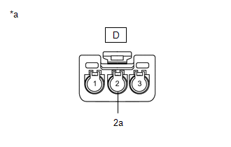
(a) Disconnect the D telephone and GPS antenna cord (No. 6 antenna cord sub-assembly) connector. |
|
|
(b) Disconnect the C telephone and GPS antenna cord (No. 6 antenna cord sub-assembly) connector. |
|
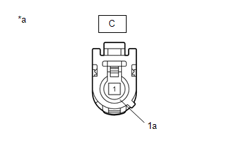
(c) Measure the resistance according to the value(s) in the table below.
Standard Resistance:
|
Tester Connection |
Condition |
Specified Condition |
|---|---|---|
|
D-2 - C-1 |
Always |
Below 1 Ω |
|
D-2 or C-1 - Body ground |
Always |
10 kΩ or higher |
|
D-2a - C-1a |
Always |
Below 1 Ω |
|
D-2a or C-1a - Body ground |
Always |
10 kΩ or higher |
| NG |
|
REPLACE TELEPHONE AND GPS ANTENNA CORD (NO. 6 ANTENNA CORD SUB-ASSEMBLY) |
|
|
3. |
INSPECT TELEPHONE AND GPS ANTENNA CORD (NO. 4 ANTENNA CORD SUB-ASSEMBLY) |
|
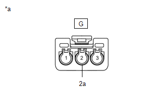
(a) Disconnect the G telephone and GPS antenna cord (No. 4 antenna cord sub-assembly) connector. |
|
|
(b) Disconnect the E telephone and GPS antenna cord (No. 4 antenna cord sub-assembly) connector. |
|
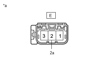
(c) Measure the resistance according to the value(s) in the table below.
Standard Resistance:
|
Tester Connection |
Condition |
Specified Condition |
|---|---|---|
|
G-2 - E-2 |
Always |
Below 1 Ω |
|
G-2 or E-2 - Body ground |
Always |
10 kΩ or higher |
|
G-2a - E-2a |
Always |
Below 1 Ω |
|
G-2a or E-2a - Body ground |
Always |
10 kΩ or higher |
| NG |
|
REPLACE TELEPHONE AND GPS ANTENNA CORD (NO. 4 ANTENNA CORD SUB-ASSEMBLY) |
|
|
4. |
INSPECT TELEPHONE AND GPS ANTENNA CORD (NO. 3 ANTENNA CORD SUB-ASSEMBLY) |
|
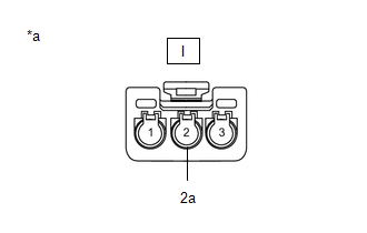
(a) Disconnect the I telephone and GPS antenna cord (No. 3 antenna cord sub-assembly) connector. |
|
|
(b) Disconnect the H telephone and GPS antenna cord (No. 3 antenna cord sub-assembly) connector. |
|
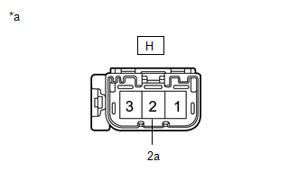
(c) Measure the resistance according to the value(s) in the table below.
Standard Resistance:
|
Tester Connection |
Condition |
Specified Condition |
|---|---|---|
|
I-2 - H-2 |
Always |
Below 1 Ω |
|
I-2 or H-2 - Body ground |
Always |
10 kΩ or higher |
|
I-2a - H-2a |
Always |
Below 1 Ω |
|
I-2a or H-2a - Body ground |
Always |
10 kΩ or higher |
| NG |
|
REPLACE TELEPHONE AND GPS ANTENNA CORD (NO. 3 ANTENNA CORD SUB-ASSEMBLY) |
|
|
5. |
INSPECT TELEPHONE AND GPS ANTENNA CORD (NO. 2 ANTENNA CORD SUB-ASSEMBLY) |
|
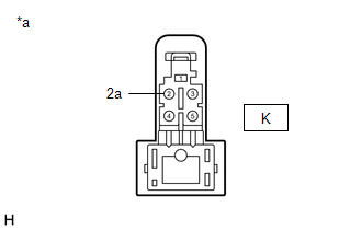
(a) Disconnect the K telephone and GPS antenna cord (No. 2 antenna cord sub-assembly) connector. |
|
|
(b) Disconnect the J telephone and GPS antenna cord (No. 2 antenna cord sub-assembly) connector. |
|
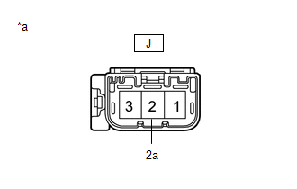
(c) Measure the resistance according to the value(s) in the table below.
Standard Resistance:
|
Tester Connection |
Condition |
Specified Condition |
|---|---|---|
|
K-2 - J-2 |
Always |
Below 1 Ω |
|
K-2 or J-2 - Body ground |
Always |
10 kΩ or higher |
|
K-2a - J-2a |
Always |
Below 1 Ω |
|
K-2a or J-2a - Body ground |
Always |
10 kΩ or higher |
| NG |
|
REPLACE TELEPHONE AND GPS ANTENNA CORD (NO. 2 ANTENNA CORD SUB-ASSEMBLY) |
|
|
6. |
REPLACE TELEPHONE AND GPS ANTENNA ASSEMBLY (for Roof Side) |
(a) Replace the telephone and GPS antenna assembly (for Roof Side) with a known good one and check if the same problem occurs again.
Click here
OK:
The system returns to normal.
| OK |
|
END |
| NG |
|
|
7. |
REPLACE DCM (TELEMATICS TRANSCEIVER) |
(a) Replace the DCM (Telematics Transceiver).
Click here
NOTICE:
- The engine switch must be off.
- Do not swap the DCM (Telematics Transceiver) with one from another vehicle.
| NEXT |
|
|
|
|