| Last Modified: 09-10-2025 | 6.11:8.1.0 | Doc ID: RM100000001B7KL |
| Model Year Start: 2019 | Model: Avalon HV | Prod Date Range: [04/2018 - ] |
| Title: LIGHTING (INT): LIGHTING SYSTEM (for HV Model): Ambient Light Switch Circuit; 2019 - 2022 MY Avalon HV [04/2018 - ] | ||
|
Ambient Light Switch Circuit |
DESCRIPTION
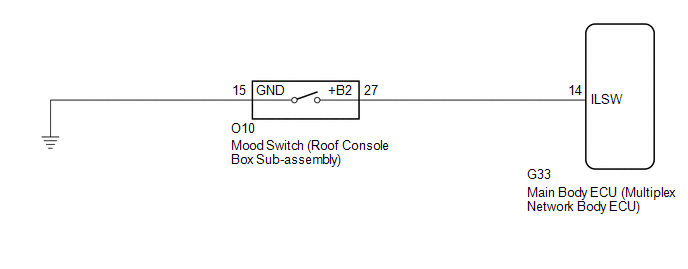
The main body ECU (multiplex network body ECU) detects the condition of the mood switch on the roof console box sub-assembly using this circuit.
WIRING DIAGRAM
CAUTION / NOTICE / HINT
NOTICE:
Before replacing the main body ECU (multiplex network body ECU), refer to Registration.
Click here
![2019 - 2020 MY Avalon HV [04/2018 - 08/2020]; THEFT DETERRENT / KEYLESS ENTRY: SMART KEY SYSTEM (for Start Function, HV Model): REGISTRATION](/t3Portal/stylegraphics/info.gif)
PROCEDURE
PROCEDURE
|
1. |
READ VALUE USING TECHSTREAM |
(a) Connect the Techstream to the DLC3.
(b) Turn the power switch on (IG).
(c) Turn the Techstream on.
(d) Enter the following menus: Body Electrical / Main Body / Data List.
(e) Read the Data List according to the display on the Techstream.
Body Electrical > Main Body > Data List
|
Tester Display |
Measurement Item |
Range |
Normal Condition |
Diagnostic Note |
|---|---|---|---|---|
|
Ceiling Light SW |
Mood switch signal |
OFF or ON |
OFF: Mood switch not pressed ON: Mood switch pressed |
- |
Body Electrical > Main Body > Data List
|
Tester Display |
|---|
|
Ceiling Light SW |
OK:
Normal conditions listed above are displayed.
| OK |

|
PROCEED TO NEXT SUSPECTED AREA SHOWN IN PROBLEM SYMPTOMS TABLE |
| NG |
|
|
2. |
INSPECT MOOD SWITCH (ROOF CONSOLE BOX SUB-ASSEMBLY) |
(a) Remove the mood switch (roof console box sub-assembly).
Click here
(b) Inspect the mood switch (roof console box sub-assembly).
Click here
| NG |
|
|

|
3. |
CHECK HARNESS AND CONNECTOR (MOOD SWITCH (ROOF CONSOLE BOX SUB-ASSEMBLY) - MAIN BODY ECU (MULTIPLEX NETWORK BODY ECU) AND BODY GROUND) |
(a) Disconnect the G33 main body ECU (multiplex network body ECU) connector.
(b) Measure the resistance according to the value(s) in the table below.
Standard Resistance:
|
Tester Connection |
Condition |
Specified Condition |
|---|---|---|
|
O10-27 (+B2) - G33-14 (ILSW) |
Always |
Below 1 Ω |
|
O10-27 (+B2) or G33-14 (ILSW) - Body ground |
Always |
10 kΩ or higher |
|
O10-15 (GND) - Body ground |
Always |
Below 1 Ω |
| OK |
|
REPLACE MAIN BODY ECU (MULTIPLEX NETWORK BODY ECU) Click here
|
| NG |
|
REPAIR OR REPLACE HARNESS OR CONNECTOR |
|
|
|