| 
                     
                        | Last Modified: 08-21-2023 | 6.11:8.1.0 | Doc ID: RM100000001B4M7 |  
                        | Model Year Start: 2019 | Model: Avalon HV | Prod Date Range: [04/2018 -                    
                                       ] |  
                        | Title: A25A-FXS (FUEL): FUEL PUMP (for High Pressure): INSTALLATION; 2019 - 2022 MY Avalon HV [04/2018 -        ] |  INSTALLATIONCAUTION / NOTICE / HINTNOTICE: This procedure includes the installation of small-head bolts. Refer to Small-Head Bolts of Basic Repair Hint to identify the small-head bolts. Click here
                        
                           
                              ![2019 - 2022 MY Avalon Avalon HV [04/2018 -        ]; INTRODUCTION: REPAIR INSTRUCTION: PRECAUTION](/t3Portal/stylegraphics/info.gif)  PROCEDURE1. TEMPORARILY INSTALL FUEL (ENGINE ROOM SIDE) PUMP ASSEMBLY NOTICE: When replacing the fuel pump assembly, it is necessary to replace the No. 1 fuel pipe sub-assembly with a new one. HINT: Perform "Inspection After Repair" after replacing the fuel pump assembly. Click here
                        
                           
                              ![2019 MY Avalon HV [04/2018 - 08/2019]; A25A-FXS (ENGINE CONTROL): SFI SYSTEM: INITIALIZATION](/t3Portal/stylegraphics/info.gif)  ![2020 - 2021 MY Avalon HV [08/2019 - 08/2021]; A25A-FXS (ENGINE CONTROL): SFI SYSTEM: INITIALIZATION](/t3Portal/stylegraphics/info.gif)  ![2022 MY Avalon HV [08/2021 -        ]; A25A-FXS (ENGINE CONTROL): SFI SYSTEM: INITIALIZATION](/t3Portal/stylegraphics/info.gif)  
                     
                        
                           | (a) Turn the crankshaft pulley until the flat of the camshaft faces the fuel pump lifter assembly. HINT: This prevents the camshaft nose from pushing up the fuel pump lifter assembly when installing the fuel pump assembly. | 
                                 
                                    |   |  
                                    | 


                                                | *1 | Fuel Pump Assembly |  
                                                | *2 | Fuel Pump Lifter Assembly |  
                                                | *3 | No. 2 Camshaft |  
                                                | *a | Correct |  
                                                | *b | Incorrect |  |  |  
                     
                        
                           | (b) Apply 30 cc (1.8 cu. in.) of engine oil to the pump drive cam. | 
                                 
                                    |   |  
                                    | 


                                                | *1 | Cylinder Head Cover Sub-assembly |  
                                                | *2 | Fuel Pump Spacer Gasket |  
                                                | *a | Pump Drive Cam (Engine Oil Application Area) |  
                                                | *b | Fuel Pump Lifter Assembly (Engine Oil Application Area) |  |  |  (c) Apply engine oil to the fuel pump lifter assembly. (d) Install a new fuel pump spacer gasket to the cylinder head cover sub-assembly. 
                     
                        
                           | (e) Apply engine oil to the inside of the fuel pump lifter guide and the outside of the fuel pump lifter assembly. | 
                                 
                                    |   |  
                                    | 


                                                | *a | Fuel Pump Lifter Assembly (Engine Oil Application Area) |  
                                                | *b | Fuel Pump Lifter Guide (Engine Oil Application Area) |  
                                                | *c | Stopper Key |  
                                                | *d | Key Groove |  |  |  
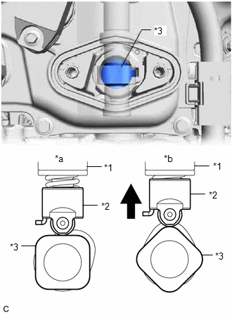
(f) Set the fuel pump lifter assembly on the fuel pump lifter guide as shown in the illustration. HINT: Align the stopper key of the fuel pump lifter assembly with the key groove of the fuel pump lifter guide. (g) Apply engine oil to a new O-ring and install it to the fuel pump assembly. NOTICE: Do not damage the O-ring. 
                     
                        
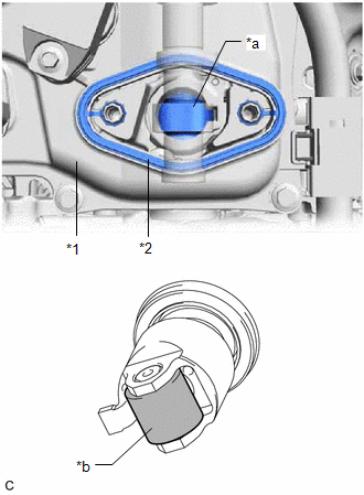
                           | (h) Set the fuel pump flange and fuel pump assembly on the cylinder head cover sub-assembly as shown in the illustration. | 
                                 
                                    |   |  
                                    | 


                                                | *1 | Fuel Pump Assembly |  
                                                | *2 | Fuel Pump Flange |  |  |  (i) Temporarily install the fuel pump assembly with the 2 bolts, leaving some allowance for left and right movement. 2. TEMPORARILY INSTALL NO. 1 FUEL PIPE SUB-ASSEMBLY NOTICE: Do not damage the seals of the union nuts of the No. 1 fuel pipe sub-assembly. (a) Temporarily install the bolt. (b) Temporarily install the No. 1 fuel pipe sub-assembly to the fuel delivery pipe and tighten the union nut by hand. (c) Temporarily install the No. 1 fuel pipe sub-assembly to the fuel pump assembly and tighten the union nut by hand. 
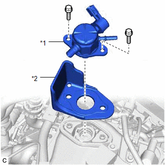
3. INSTALL FUEL (ENGINE ROOM SIDE) PUMP ASSEMBLY (a) Tighten the 2 bolts. Torque:  28.5 N·m {291 kgf·cm, 21 ft·lbf} (b) Connect the fuel pump assembly connector. 4. INSTALL NO. 1 FUEL PIPE SUB-ASSEMBLY 
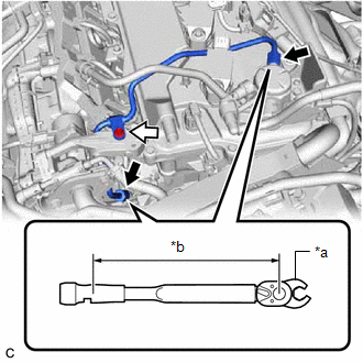
(a) for EGR Valve Bracket Connection Type: (1) Using a 17 mm union nut wrench, tighten the union nut on the fuel delivery pipe side of the No. 1 fuel pipe sub-assembly.   


                           | *a | 17 mm Union Nut Wrench |  
                           | *b | Torque Wrench Fulcrum Length |  
                           |   | Union Nut |  
                           |   | Bolt |  Torque:  Specified tightening torque :   35 N·m {357 kgf·cm, 26 ft·lbf} NOTICE: Do not adjust the torque in the loosening direction. 
                     HINT: 
                        
Calculate the torque wrench reading when changing the fulcrum length of the torque wrench.
Click here
                                 
                                    
                                       ![2019 - 2022 MY Avalon Avalon HV [04/2018 -        ]; INTRODUCTION: REPAIR INSTRUCTION: PRECAUTION](/t3Portal/stylegraphics/info.gif) 
When using a 17 mm union nut wrench (fulcrum length of 30 mm (1.18 in.)) + torque wrench (fulcrum length of 180 mm (7.09 in.)): 30 N*m (306 kgf*cm, 22 ft.*lbf)
 (2) Using a 17 mm union nut wrench, tighten the union nut on the fuel pump assembly side of the No. 1 fuel pipe sub-assembly. Torque:  Specified tightening torque :   35 N·m {357 kgf·cm, 26 ft·lbf} NOTICE: Do not adjust the torque in the loosening direction. 
                     HINT: 
                        
Calculate the torque wrench reading when changing the fulcrum length of the torque wrench.
Click here
                                 
                                    
                                       ![2019 - 2022 MY Avalon Avalon HV [04/2018 -        ]; INTRODUCTION: REPAIR INSTRUCTION: PRECAUTION](/t3Portal/stylegraphics/info.gif) 
When using a 17 mm union nut wrench (fulcrum length of 30 mm (1.18 in.)) + torque wrench (fulcrum length of 180 mm (7.09 in.)): 30 N*m (306 kgf*cm, 22 ft.*lbf)
 (3) Using an 8 mm socket wrench, tighten the bolt. Torque:  10 N·m {102 kgf·cm, 7 ft·lbf} 
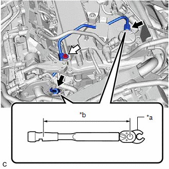
(b) for Cylinder Head Cover Sub-assembly Connection Type: (1) Using a 17 mm union nut wrench, tighten the union nut on the fuel delivery pipe side of the No. 1 fuel pipe sub-assembly.   


                           | *a | 17 mm Union Nut Wrench |  
                           | *b | Torque Wrench Fulcrum Length |  
                           |   | Union Nut |  
                           |   | Bolt |  Torque:  Specified tightening torque :   35 N·m {357 kgf·cm, 26 ft·lbf} NOTICE: Do not adjust the torque in the loosening direction. 
                     HINT: 
                        
Calculate the torque wrench reading when changing the fulcrum length of the torque wrench.
Click here
                                 
                                    
                                       ![2019 - 2022 MY Avalon Avalon HV [04/2018 -        ]; INTRODUCTION: REPAIR INSTRUCTION: PRECAUTION](/t3Portal/stylegraphics/info.gif) 
When using a 17 mm union nut wrench (fulcrum length of 30 mm (1.18 in.)) + torque wrench (fulcrum length of 180 mm (7.09 in.)): 30 N*m (306 kgf*cm, 22 ft.*lbf)
 (2) Using a 17 mm union nut wrench, tighten the union nut on the fuel pump assembly side of the No. 1 fuel pipe sub-assembly. Torque:  Specified tightening torque :   35 N·m {357 kgf·cm, 26 ft·lbf} NOTICE: Do not adjust the torque in the loosening direction. 
                     HINT: 
                        
Calculate the torque wrench reading when changing the fulcrum length of the torque wrench.
Click here
                                 
                                    
                                       ![2019 - 2022 MY Avalon Avalon HV [04/2018 -        ]; INTRODUCTION: REPAIR INSTRUCTION: PRECAUTION](/t3Portal/stylegraphics/info.gif) 
When using a 17 mm union nut wrench (fulcrum length of 30 mm (1.18 in.)) + torque wrench (fulcrum length of 180 mm (7.09 in.)): 30 N*m (306 kgf*cm, 22 ft.*lbf)
 (3) Using an 8 mm socket wrench, tighten the bolt. Torque:  10 N·m {102 kgf·cm, 7 ft·lbf} (c) Connect the ignition coil assembly connector. 5. INSTALL NO. 2 WATER BY-PASS PIPE 
                     
                        
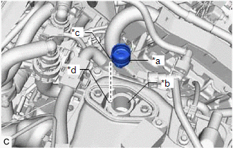
                           | (a) Temporarily install the No. 2 water by-pass pipe to the cylinder block sub-assembly with the bolt (B). |  |  
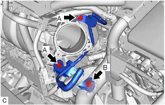
(b) Using an 8 mm socket wrench, temporarily install the No. 2 water by-pass pipe to the intake manifold with the 2 bolts (A). (c) Tighten the bolt (B). Torque:  21 N·m {214 kgf·cm, 15 ft·lbf} (d) Using the 8 mm socket wrench, tighten the 2 bolts (A). Torque:  10 N·m {102 kgf·cm, 7 ft·lbf} 
                     
                        
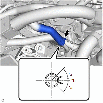
                           | (e) Connect the No. 8 water by-pass hose to the No. 2 water by-pass pipe and slide the clip to secure it. HINT: Engage the clip within the area shown in the illustration. | 
                                 
                                    |   |  
                                    | 


                                                | *a | 45° |  
                                                | *b | Left Side of Vehicle |  |  |  (f) Engage the clamp to connect the HV air conditioning wire. 6. CONNECT FUEL TUBE SUB-ASSEMBLY (a) Connect the fuel tube sub-assembly to the fuel pump assembly and fuel delivery pipe. Click here
                        
                           
                              ![2019 - 2022 MY Avalon HV [04/2018 -        ]; A25A-FXS (FUEL): FUEL SYSTEM: PRECAUTION](/t3Portal/stylegraphics/info.gif)  (b) Install the fuel pipe clamp to the fuel tube connector. 7. INSTALL THROTTLE BODY WITH MOTOR ASSEMBLY Click here
                        
                           
                              ![2019 - 2022 MY Avalon HV [04/2018 -        ]; A25A-FXS (ENGINE CONTROL): THROTTLE BODY: INSTALLATION](/t3Portal/stylegraphics/info.gif)  8. CONNECT CABLE TO NEGATIVE AUXILIARY BATTERY TERMINAL Click here
                        
                           
                              ![2019 - 2022 MY Avalon HV [04/2018 -        ]; MAINTENANCE: A25A-FXS AUXILIARY BATTERY: INSTALLATION+](/t3Portal/stylegraphics/info.gif)  9. INSTALL LUGGAGE TRIM SERVICE HOLE COVER Click here
                        
                           
                              ![2019 - 2022 MY Avalon HV [04/2018 -        ]; MAINTENANCE: A25A-FXS AUXILIARY BATTERY: INSTALLATION+](/t3Portal/stylegraphics/info.gif)  10. INSPECT FOR FUEL LEAK Click here
                        
                           
                              ![2019 - 2022 MY Avalon HV [04/2018 -        ]; A25A-FXS (FUEL): FUEL SYSTEM: ON-VEHICLE INSPECTION+](/t3Portal/stylegraphics/info.gif)  11. PERFORM INITIALIZATION (a) Perform "Inspection After Repair" after replacing the fuel pump assembly. Click here
                        
                           
                              ![2019 MY Avalon HV [04/2018 - 08/2019]; A25A-FXS (ENGINE CONTROL): SFI SYSTEM: INITIALIZATION](/t3Portal/stylegraphics/info.gif)  ![2020 - 2021 MY Avalon HV [08/2019 - 08/2021]; A25A-FXS (ENGINE CONTROL): SFI SYSTEM: INITIALIZATION](/t3Portal/stylegraphics/info.gif)  ![2022 MY Avalon HV [08/2021 -        ]; A25A-FXS (ENGINE CONTROL): SFI SYSTEM: INITIALIZATION](/t3Portal/stylegraphics/info.gif)  |