| Last Modified: 08-21-2023 | 6.11:8.1.0 | Doc ID: RM100000001B4LP |
| Model Year Start: 2019 | Model: Avalon HV | Prod Date Range: [04/2018 - 08/2021] |
| Title: A25A-FXS (FUEL): FUEL MAIN VALVE: REMOVAL; 2019 - 2021 MY Avalon HV [04/2018 - 08/2021] | ||
REMOVAL
CAUTION / NOTICE / HINT
The necessary procedures (adjustment, calibration, initialization or registration) that must be performed after parts are removed and installed, or replaced during fuel main valve assembly removal/installation are shown below.
Necessary Procedures After Parts Removed/Installed/Replaced
|
Replaced Part or Performed Procedure |
Necessary Procedure |
Effect/Inoperative Function when Necessary Procedure not Performed |
Link |
|---|---|---|---|
|
*: When performing learning using the Techstream.
Click here
|
|||
|
Auxiliary battery terminal is disconnected/reconnected |
Perform steering sensor zero point calibration |
Lane Departure Alert System (w/ Steering Control) |
|
|
Pre-collision System |
|||
|
Intelligent Clearance Sonar System* |
|||
|
Lighting System (for HV Model with Cornering Light) |
|||
|
Memorize steering angle neutral point |
Parking Assist Monitor System |
|
|
|
Panoramic View Monitor System |
|
||
CAUTION:
-
Never perform work on fuel system components near any possible ignition sources.
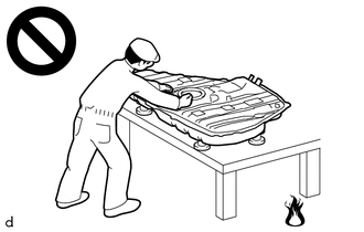
- Vaporized fuel could ignite, resulting in a serious accident.
-
Do not perform work on fuel system components without first disconnecting the cable from the negative (-) auxiliary battery terminal.
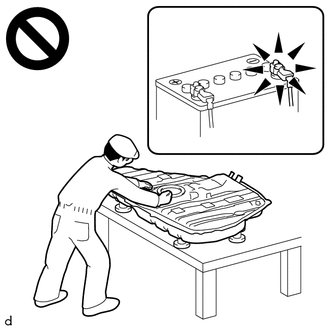
- Sparks could cause vaporized fuel to ignite, resulting in a serious accident.
PROCEDURE
1. REMOVE FUEL SUCTION TUBE WITH PUMP AND GAUGE ASSEMBLY
Click here
![2019 - 2021 MY Avalon HV [04/2018 - 08/2021]; A25A-FXS (FUEL): FUEL PUMP: REMOVAL](/t3Portal/stylegraphics/info.gif)
2. REMOVE FUEL MAIN VALVE ASSEMBLY
(a) for Type A:
|
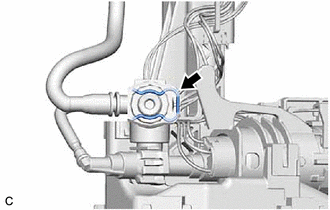
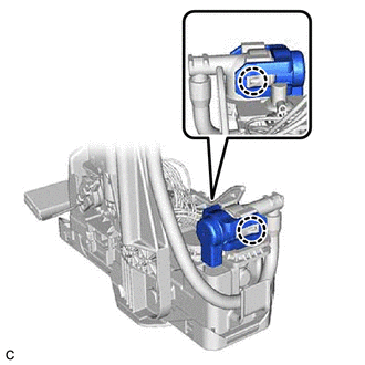
(1) Remove the clip from the fuel suction tube with pump and gauge assembly. |
|
|
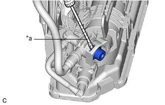
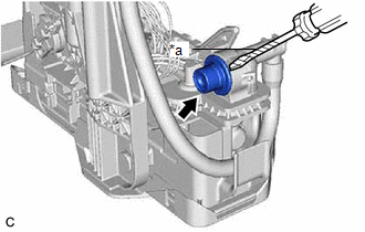
(2) Using a screwdriver with its tip wrapped with protective tape, remove the fuel main valve assembly from the fuel suction tube with pump and gauge assembly. NOTICE:
|
|
|
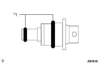
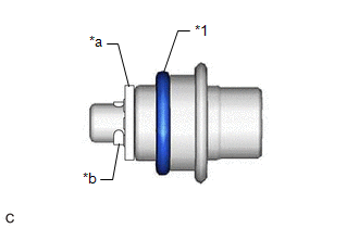
(3) Remove the 2 O-rings from the fuel main valve assembly. |
|
(b) for Type B:
|
(1) Disengage the 2 claws and remove the fuel pressure regulator holder from the fuel suction tube with pump and gauge assembly. |
|
|
(2) Using a screwdriver with its tip wrapped with protective tape, remove the fuel main valve assembly from the fuel suction tube with pump and gauge assembly. NOTICE:
|
|
|
(3) Remove the O-ring from the fuel main valve assembly. NOTICE: Do not remove the mesh and mini-clip from the fuel main valve assembly. |
|
|
|
|