| 
                     
                        | Last Modified: 08-21-2023 | 6.11:8.1.0 | Doc ID: RM100000001B3SD |  
                        | Model Year Start: 2019 | Model: Avalon HV | Prod Date Range: [04/2018 - 08/2020] |  
                        | Title: HYBRID / BATTERY CONTROL: HV BATTERY THERMISTOR (for NICKEL METAL HYDRIDE BATTERY): INSTALLATION; 2019 - 2020 MY Avalon HV [04/2018 - 08/2020] |  INSTALLATIONPROCEDURE1. INSTALL HYBRID BATTERY THERMISTOR CAUTION: Be sure to wear insulated gloves and protective goggles. 
                     
                        
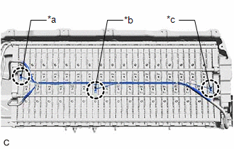
                           | (a) Engage the 3 claws of the hybrid battery thermistor (sensor portions) to install the hybrid battery thermistor to the HV battery. HINT: Install each hybrid battery thermistor (sensor portion) to the appropriate location shown in the illustration. | 
                                 
                                    |   |  
                                    | 


                                                | *a | 1st Module from the HV Battery Junction Block Assembly Side (Wire harness color: Blue) |  
                                                | *b | 14th Module from the HV Battery Junction Block Assembly Side (Wire harness color: White) |  
                                                | *c | 34th Module from the HV Battery Junction Block Assembly Side (Wire harness color: Red) |  |  |  
                     
                        
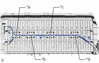
                           | (b) Engage the 4 clamps in the locations shown in the illustration. | 
                                 
                                    |   |  
                                    | 


                                                | *a | 4th Module from the HV Battery Junction Block Assembly Side |  
                                                | *b | 10th Module from the HV Battery Junction Block Assembly Side |  
                                                | *c | 18th Module from the HV Battery Junction Block Assembly Side |  
                                                | *d | 28th Module from the HV Battery Junction Block Assembly Side |  |  |  (c) Connect the battery voltage sensor connector. (d) Engage the clamp. 
                     
                        
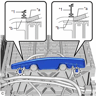
                           | (e) Engage the 2 claws to install the No. 1 hybrid battery packing to the HV battery. NOTICE: Align each piece of tape on the wire harness of the hybrid battery thermistor with the edge of the No. 1 hybrid battery packing as shown in the illustration and then engage the 2 claws to install the No. 1 hybrid battery packing to the HV battery. | 
                                 
                                    |   |  
                                    | 


                                                | *1 | No. 1 Hybrid Battery Packing |  
                                                | *a | Tape |  
                                                | *b | Hybrid Battery Thermistor Wire Harness |  |  |  (f) Engage the clamp. 2. INSTALL NO. 1 HV BATTERY INTAKE DUCT LH CAUTION: Be sure to wear insulated gloves and protective goggles. (a) Install the No. 1 HV battery intake duct LH to the HV battery with the clip. (b) Engage the claw of hybrid battery thermistor (sensor portion) to connect the hybrid battery thermistor to the No. 1 HV battery intake duct LH. 3. INSTALL NO. 2 HYBRID BATTERY SHIELD SUB-ASSEMBLY CAUTION: Be sure to wear insulated gloves and protective goggles. (a) Pull back the rear No. 1 HV battery shield and install the No. 2 hybrid battery shield sub-assembly to the HV battery. HINT: Pull back the rear No. 1 HV battery shield until there is sufficient clearance for the stud bolt of the No. 2 hybrid battery shield sub-assembly. (b) Install the 5 nuts. Torque:  7.5 N·m {76 kgf·cm, 66 in·lbf} 4. INSTALL HV BATTERY JUNCTION BLOCK ASSEMBLY Click here
                        
                           
                              ![2019 - 2020 MY Avalon HV [04/2018 - 08/2020]; HYBRID / BATTERY CONTROL: HV RELAY ASSEMBLY (for NICKEL METAL HYDRIDE BATTERY): INSTALLATION+](/t3Portal/stylegraphics/info.gif)  5. INSTALL UPPER HV BATTERY COVER SUB-ASSEMBLY Click here
                        
                           
                              ![2019 - 2020 MY Avalon HV [04/2018 - 08/2020]; HYBRID / BATTERY CONTROL: BATTERY VOLTAGE SENSOR (for NICKEL METAL HYDRIDE BATTERY): INSTALLATION+](/t3Portal/stylegraphics/info.gif)  6. INSTALL HV BATTERY Click here
                        
                           
                              ![2019 - 2020 MY Avalon HV [04/2018 - 08/2020]; HYBRID / BATTERY CONTROL: HV BATTERY (for NICKEL METAL HYDRIDE BATTERY): INSTALLATION](/t3Portal/stylegraphics/info.gif)  |