| 
                     
                        | Last Modified: 08-21-2023 | 6.11:8.1.0 | Doc ID: RM100000001B1Z0 |  
                        | Model Year Start: 2019 | Model: Avalon HV | Prod Date Range: [04/2018 -                    
                                       ] |  
                        | Title: PARK ASSIST / MONITORING: TELEVISION CAMERA(for Side): REMOVAL; 2019 - 2022 MY Avalon Avalon HV [04/2018 -        ] |  REMOVALCAUTION / NOTICE / HINTThe necessary procedures (adjustment, calibration, initialization, or registration) that must be performed after parts are removed and installed, or replaced during side television camera assembly removal/installation are shown below. Necessary Procedure After Parts Removed/Installed/Replaced (for Gasoline Model)


                           | Replaced Part or Performed Procedure | Necessary Procedure | Effect/Inoperative Function When Necessary Procedures are not Performed | Link |  
                           | 
                                 
                                    
Side television camera assembly LH
Side television camera assembly RH
 | Side television camera view adjustment | Panoramic View Monitor System | 


                                          ![2019 - 2022 MY Avalon [04/2018 -        ]; PARK ASSIST / MONITORING: PANORAMIC VIEW MONITOR SYSTEM (for Gasoline Model): CALIBRATION](/t3Portal/stylegraphics/info.gif)  |  Necessary Procedure After Parts Removed/Installed/Replaced (for HV Model)


                           | Replaced Part or Performed Procedure | Necessary Procedure | Effect/Inoperative Function When Necessary Procedures are not Performed | Link |  
                           | 
                                 
                                    
Side television camera assembly LH
Side television camera assembly RH
 | Side television camera view adjustment | Panoramic View Monitor System | 


                                          ![2019 - 2022 MY Avalon HV [04/2018 -        ]; PARK ASSIST / MONITORING: PANORAMIC VIEW MONITOR SYSTEM (for HV Model): CALIBRATION](/t3Portal/stylegraphics/info.gif)  |  PROCEDURE1. REMOVE OUTER REAR VIEW MIRROR ASSEMBLY WITH COVER Click here
                        
                           
                              ![2019 - 2022 MY Avalon Avalon HV [04/2018 -        ]; MIRROR (EXT): OUTER REAR VIEW MIRROR: REMOVAL](/t3Portal/stylegraphics/info.gif)  2. REMOVE OUTER MIRROR Click here
                        
                           
                              ![2019 - 2022 MY Avalon Avalon HV [04/2018 -        ]; MIRROR (EXT): OUTER REAR VIEW MIRROR GLASS: REMOVAL+](/t3Portal/stylegraphics/info.gif)  3. REMOVE OUTER MIRROR COVER Click here
                        
                           
                              ![2019 - 2022 MY Avalon Avalon HV [04/2018 -        ]; MIRROR (EXT): OUTER REAR VIEW MIRROR COVER: REMOVAL+](/t3Portal/stylegraphics/info.gif)  4. REMOVE VISOR HOUSING Click here
                        
                           
                              ![2019 - 2022 MY Avalon Avalon HV [04/2018 -        ]; MIRROR (EXT): OUTER REAR VIEW MIRROR: DISASSEMBLY+](/t3Portal/stylegraphics/info.gif)  5. REMOVE SIDE TELEVISION CAMERA ASSEMBLY 
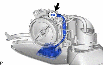
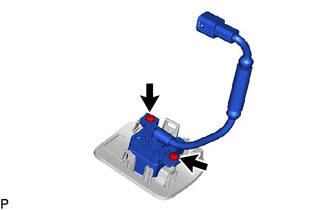
                     
                        
                           | (b) Insert a 0.9 mm (0.0354 in.) spark plug gap gauge or similar tool into the connector as shown in the illustration. 
                                 NOTICE: 
                                    
Insert the spark plug gap gauge to the point that the claw becomes the same height as the protrusion of the connector housing. If the spark plug gap gauge is inserted too far, or if the claw is lifted directly using a screwdriver, the claw may be damaged.
If the claw of the connector is damaged, replace the outer rear view mirror assembly.
 | 
                                 
                                    |   |  
                                    | 


                                                | *a | Claw |  
                                                | *b | Protrusion |  
                                                | *c | Insert Position |  |  |  
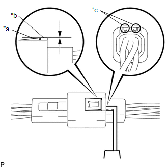
(c) Lift the claw and disconnect the connector. 
                     
                        
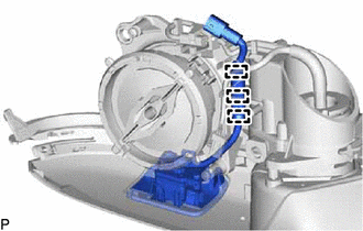
                           | (d) Disengage the 3 guides. |  |  
                     
                        
                           | (e) Disengage the 4 claws. |  |  (f) Disengage the 3 guides as shown in the illustration.   


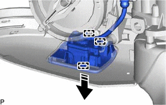
                           |   | Remove in this Direction |  
                     
                        
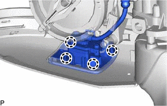
                           | (g) Using a T10 "TORX" driver, remove the 2 screws to remove the side television camera assembly from the camera cover. |  |  |