| Last Modified: 09-10-2025 | 6.11:8.1.0 | Doc ID: RM100000001B1XV |
| Model Year Start: 2019 | Model: Avalon | Prod Date Range: [04/2018 - ] |
| Title: PARK ASSIST / MONITORING: BLIND SPOT MONITOR SYSTEM (for Gasoline Model): C1AB2; Short to GND in Outer Mirror Indicator(Master); 2019 - 2022 MY Avalon [04/2018 - ] | ||
|
DTC |
C1AB2 |
Short to GND in Outer Mirror Indicator(Master) |
DESCRIPTION
This DTC is stored when the blind spot monitor sensor RH detects a short to ground in the outer rear view mirror indicator RH.
|
DTC No. |
Detection Item |
DTC Detection Condition |
Trouble Area |
|---|---|---|---|
|
C1AB2 |
Short to GND in Outer Mirror Indicator(Master) |
Both of the following conditions are met:
|
|
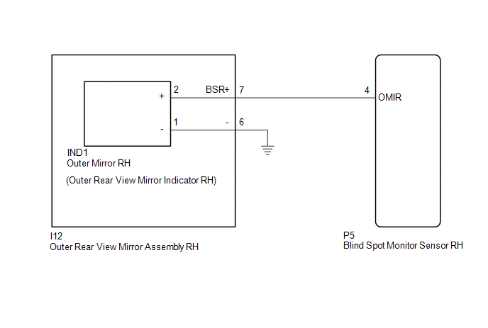
WIRING DIAGRAM
w/o Seat Memory
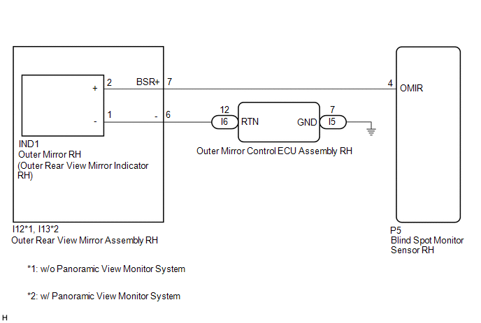
w/ Seat Memory
CAUTION / NOTICE / HINT
NOTICE:
When checking for DTCs, make sure that the blind spot monitor system is turned on.
PROCEDURE
PROCEDURE
|
1. |
CHECK DTC |
(a) Turn the engine switch off.
(b) Turn the engine switch on (IG).
(c) Recheck for DTCs and check if the same DTC is output again.
Body Electrical > Blind Spot Monitor Master > Trouble Codes
OK:
No DTCs are output.
| OK |

|
| NG |
|
|
2. |
CHECK HARNESS AND CONNECTOR (BLIND SPOT MONITOR SENSOR RH - OUTER REAR VIEW MIRROR ASSEMBLY RH) |
(a) Disconnect the P5 blind spot monitor sensor RH connector.
(b) Disconnect the I12*1 or I13*2 outer rear view mirror assembly RH connector.
(c) Measure the resistance according to the value(s) in the table below.
Standard Resistance:
|
Tester Connection |
Condition |
Specified Condition |
|---|---|---|
|
P5-4 (OMIR) or I12-7 (BSR+) - Body ground*1 |
Always |
10 kΩ or higher |
|
P5-4 (OMIR) or I13-7 (BSR+) - Body ground*2 |
Always |
10 kΩ or higher |
- *1: w/o Panoramic View Monitor System
- *2: w/ Panoramic View Monitor System
| NG |
|
REPAIR OR REPLACE HARNESS OR CONNECTOR |
|

|
3. |
INSPECT OUTER REAR VIEW MIRROR ASSEMBLY RH |
(a) Disconnect the IND1 outer mirror RH connector.
(b) Measure the resistance according to the value(s) in the table below.
Standard Resistance:
|
Tester Connection |
Condition |
Specified Condition |
|---|---|---|
|
I12-7 (BSR+) or IND1-2 (+) - Body ground*1 |
Always |
10 kΩ or higher |
|
I13-7 (BSR+) or IND1-2 (+) - Body ground*2 |
Always |
10 kΩ or higher |
- *1: w/o Panoramic View Monitor System
- *2: w/ Panoramic View Monitor System
| NG |
|
|
|
4. |
INSPECT OUTER MIRROR RH |
(a) Remove the outer mirror RH.
Click here
![2019 - 2022 MY Avalon Avalon HV [04/2018 - ]; MIRROR (EXT): OUTER REAR VIEW MIRROR GLASS: REMOVAL](/t3Portal/stylegraphics/info.gif)
(b) Inspect the outer rear view mirror indicator RH on the outer mirror RH.
Click here
| OK |
|
| NG |
|
|
|
|