- Engine switch on (IG)
- Mirror heater switch (rear window defogger switch) on
| Last Modified: 08-21-2023 | 6.11:8.1.0 | Doc ID: RM100000001AZJ3 |
| Model Year Start: 2019 | Model: Avalon | Prod Date Range: [04/2018 - ] |
| Title: MIRROR (EXT): POWER MIRROR CONTROL SYSTEM (for Gasoline Model with Memory): TERMINALS OF ECU; 2019 - 2022 MY Avalon [04/2018 - ] | ||
TERMINALS OF ECU
CHECK OUTER MIRROR CONTROL ECU ASSEMBLY LH
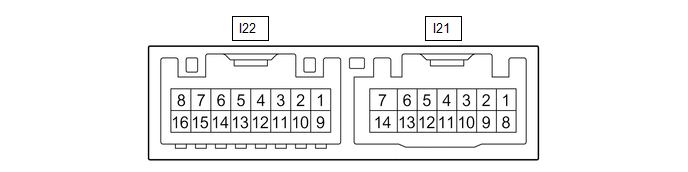
(a) Disconnect the I21 outer mirror control ECU assembly LH connector.
(b) Measure the voltage and resistance according to the value(s) in the table below.
HINT:
Measure the values on the wire harness side with the connector disconnected.
|
Terminal No. (Symbol) |
Wiring Color |
Terminal Description |
Condition |
Specified Condition |
|---|---|---|---|---|
|
I21-14 (BDR) - Body ground |
GR - Body ground |
+B power supply |
Always |
11 to 14 V |
|
I21-6 (CPUB) - Body ground |
LA-L - Body ground |
+B power supply |
Always |
11 to 14 V |
|
I21-5 (SIG) - Body ground |
LA-B - Body ground |
Ignition power supply |
Engine switch off → on (IG) |
Below 1 V → 11 to 14 V |
|
I21-7 (GND) - Body ground |
W-B - Body ground |
Ground |
Always |
Below 1 Ω |
(c) Reconnect the I21 outer mirror control ECU assembly LH connector.
(d) Measure the voltage according to the value(s) in the table below.
|
Terminal No. (Symbol) |
Wiring Color |
Terminal Description |
Condition |
Specified Condition |
|---|---|---|---|---|
|
I22-1 (LMVR) - I22-10 (LM+R) |
BR - V |
Vertical mirror motor drive voltage |
Driver door mirror surface moving upward → stopped |
11 to 14 V → Below 1 V |
|
I22-10 (LM+R) - I22-1 (LMVR) |
V - BR |
Vertical mirror motor drive voltage |
Driver door mirror surface moving downward → stopped |
11 to 14 V → Below 1 V |
|
I22-10 (LM+R) - I22-9 (LMHR) |
V - LG |
Horizontal mirror motor drive voltage |
Driver door mirror surface moving right → stopped |
11 to 14 V → Below 1 V |
|
I22-9 (LMHR) - I22-10 (LM+R) |
LG - V |
Horizontal mirror motor drive voltage |
Driver door mirror surface moving left → stopped |
11 to 14 V → Below 1 V |
|
I22-5 (LVC) - I22-14 (LE1) |
G - BR |
Mirror position sensor power supply |
Engine switch on (IG) |
4.55 to 5.45 V |
|
Engine switch off |
Below 1 V |
|||
|
I22-6 (VSSR) - I21-7 (GND) |
V - W-B |
Mirror position sensor signal |
Engine switch on (IG) |
0 to 5 V |
|
I22-13 (HSSR) - I21-7 (GND) |
GR - W-B |
Mirror position sensor signal |
Engine switch on (IG) |
0 to 5 V |
|
I22-4 (HTR+) - I22-12 (RTN) |
LG - W |
Mirror heater drive voltage |
|
11 to 14 V |
|
I21-3 (M2) - I21-7 (GND) |
R - W-B |
M2 switch signal for seat memory switch |
M2 switch on |
Below 1 V |
|
M2 switch off |
11 to 14 V |
|||
|
I21-2 (M1) - I21-7 (GND) |
BR - W-B |
M1 switch signal for seat memory switch |
M1 switch on |
Below 1 V |
|
M1 switch off |
11 to 14 V |
|||
|
I21-1 (MM) - I21-7 (GND) |
GR - W-B |
SET switch signal for seat memory switch |
SET switch on |
Below 1 V |
|
SET switch off |
11 to 14 V |
CHECK OUTER MIRROR CONTROL ECU ASSEMBLY RH
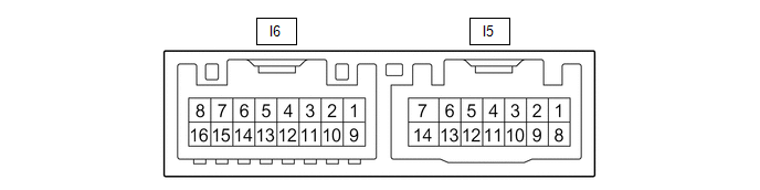
(a) Disconnect the I5 outer mirror control ECU assembly RH connector.
(b) Measure the voltage and resistance according to the value(s) in the table below.
HINT:
Measure the values on the wire harness side with the connector disconnected.
|
Terminal No. (Symbol) |
Wiring Color |
Terminal Description |
Condition |
Specified Condition |
|---|---|---|---|---|
|
I5-14 (BDR) - Body ground |
GR - Body ground |
+B power supply |
Always |
11 to 14 V |
|
I5-6 (CPUB) - Body ground |
LA-L - Body ground |
+B power supply |
Always |
11 to 14 V |
|
I5-5 (SIG) - Body ground |
LA-B - Body ground |
Ignition power supply |
Engine switch off → on (IG) |
Below 1 V → 11 to 14 V |
|
I5-7 (GND) - Body ground |
W-B - Body ground |
Ground |
Always |
Below 1 Ω |
(c) Reconnect the I5 outer mirror control ECU assembly RH connector.
(d) Measure the voltage according to the value(s) in the table below.
|
Terminal No. (Symbol) |
Wiring Color |
Terminal Description |
Condition |
Specified Condition |
|---|---|---|---|---|
|
I6-1 (RMVR) - I6-10 (RM+R) |
BR - V |
Vertical mirror motor drive voltage |
Front passenger door mirror surface moving upward → stopped |
11 to 14 V → Below 1 V |
|
I6-10 (RM+R) - I6-1 (RMVR) |
V - BR |
Vertical mirror motor drive voltage |
Front passenger door mirror surface moving downward → stopped |
11 to 14 V → Below 1 V |
|
I6-10 (RM+R) - I6-9 (RMHR) |
V - LG |
Horizontal mirror motor drive voltage |
Front passenger door mirror surface moving right → stopped |
11 to 14 V → Below 1 V |
|
I6-9 (RMHR) - I6-10 (RM+R) |
LG - V |
Horizontal mirror motor drive voltage |
Front passenger door mirror surface moving left → stopped |
11 to 14 V → Below 1 V |
|
I6-5 (RVC) - I6-14 (RE1) |
G - BR |
Mirror position sensor power supply |
Engine switch on (IG) |
4.55 to 5.45 V |
|
Engine switch off |
Below 1 V |
|||
|
I6-6 (VSSR) - I5-7 (GND) |
V - W-B |
Mirror position sensor signal |
Engine switch on (IG) |
0 to 5 V |
|
I6-13 (HSSR) - I5-7 (GND) |
GR - W-B |
Mirror position sensor signal |
Engine switch on (IG) |
0 to 5 V |
|
I6-4 (HTR+) - I6-12 (RTN) |
LG - W |
Mirror heater drive voltage |
|
11 to 14 V |
CHECK MAIN BODY ECU (MULTIPLEX NETWORK BODY ECU) AND INSTRUMENT PANEL JUNCTION BLOCK ASSEMBLY
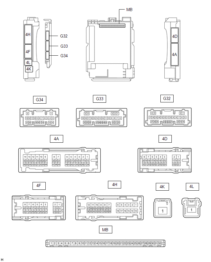
(a) Disconnect the instrument panel junction block assembly and main body ECU (multiplex network body ECU) connectors.
Click here
![2019 - 2021 MY Avalon Avalon HV [04/2018 - 08/2021]; POWER DISTRIBUTION: MAIN BODY ECU: REMOVAL](/t3Portal/stylegraphics/info.gif)
(b) Reconnect the instrument panel junction block assembly connectors.
(c) Measure the resistance and voltage according to the value(s) in the table below.
HINT:
Measure the values on the wire harness side with the connector disconnected.
|
Terminal No. (Symbol) |
Wiring Color |
Terminal Description |
Condition |
Specified Condition |
|---|---|---|---|---|
|
MB-31 (BECU) - Body ground |
- |
Battery power supply |
Always |
11 to 14 V |
|
MB-32 (IG) - Body ground |
- |
Ignition power supply (IG signal) |
Engine switch on (IG) |
11 to 14 V |
|
Engine switch off |
Below 1 V |
|||
|
MB-30 (ACC) - Body ground |
- |
Ignition power supply (ACC signal) |
Engine switch on (ACC) |
11 to 14 V |
|
Engine switch off |
Below 1 V |
|||
|
MB-11 (GND1) - Body ground |
- |
Ground |
Always |
Below 1 Ω |
|
G32-19 (GND2) - Body ground |
W-B - Body ground |
Ground |
Always |
Below 1 Ω |
(d) Connect the main body ECU (multiplex network body ECU) connectors.
(e) Measure the voltage according to the value(s) in the table below.
|
Tester Connection |
Wiring Color |
Terminal Description |
Condition |
Specified Condition |
|---|---|---|---|---|
|
G34-7 (MIRB) - G34-9 (MIRE) |
L - W |
Mirror surface adjust switch signal |
|
Below 1.7 V |
|
Below 2.7 V |
|||
|
Below 3.5 V |
|||
|
Below 4 V |
|||
|
3.8 to 5 V |
|||
|
G34-8 (MIRS) - G34-9 (MIRE) |
GR - W |
Mirror select switch signal |
|
Below 2 V |
|
Below 1 V |
|||
|
3.8 to 5.0 V |
|
|
|