| Last Modified: 09-10-2025 | 6.11:8.1.0 | Doc ID: RM100000001AZAB |
| Model Year Start: 2019 | Model: Avalon | Prod Date Range: [04/2018 - 08/2020] |
| Title: BRAKE CONTROL / DYNAMIC CONTROL SYSTEMS: ELECTRONICALLY CONTROLLED BRAKE SYSTEM (for Gasoline Model): C1237; Speed Sensor Rotor Faulty; 2019 - 2020 MY Avalon [04/2018 - 08/2020] | ||
|
DTC |
C1237 |
Speed Sensor Rotor Faulty |
DESCRIPTION
The skid control ECU (brake actuator assembly) measures the speed of each wheel by receiving signals from each speed sensor.
These signals are used for recognizing that all four wheels are operating properly.
Therefore, signals from all wheels must be equal.
|
DTC No. |
Detection Item |
DTC Detection Condition |
Trouble Area |
|---|---|---|---|
|
C1237 |
Speed Sensor Rotor Faulty |
Any of the following is detected:
|
|
DTC Detection Conditions: C1237
|
Vehicle Condition |
|||||
|---|---|---|---|---|---|
|
Pattern 1 |
Pattern 2 |
Pattern 3 |
Pattern 4 |
||
|
Diagnosis Condition |
- |
- |
- |
- |
- |
|
Malfunction Status |
Discrepancy among four wheel speed sensor output. |
○ |
- |
- |
- |
|
Abnormal pulse signals from 3 or more sensors. |
- |
○ |
- |
- |
|
|
Continuous ABS control is performed. |
- |
- |
○ |
- |
|
|
VSC control is performed. |
- |
- |
- |
○ |
|
|
Detection Time |
- |
- |
60 seconds or more |
5 seconds or more |
|
|
Number of Trips |
1 trip |
1 trip |
1 trip |
1 trip |
|
HINT:
DTC will be output when conditions for either of the patterns in the table above are met.
WIRING DIAGRAM
Refer to DTCs C1330, C1331, C1332, C1333, C1464, C1465, C1466 and C1467.
Click here
![2019 - 2020 MY Avalon [04/2018 - 08/2020]; BRAKE CONTROL / DYNAMIC CONTROL SYSTEMS: ELECTRONICALLY CONTROLLED BRAKE SYSTEM (for Gasoline Model): C1330,...,C1467; Open Circuit in Right Front Speed Sensor Circuit](/t3Portal/stylegraphics/info.gif)
CAUTION / NOTICE / HINT
NOTICE:
When replacing the skid control ECU (brake actuator assembly), perform system variant learning and acceleration sensor zero point calibration.
Click here
HINT:
When C1330, C1331, C1332, C1333, C1464, C1465, C1466 and/or C1467 is output together with C1237, inspect and repair the trouble areas indicated by C1330, C1331, C1332, C1333, C1464, C1465, C1466 and/or C1467 first.
Click here
PROCEDURE
PROCEDURE
|
1. |
CHECK DTC |
(a) Check the DTCs that are output.
Chassis > ABS/VSC/TRAC/EPB > Trouble Codes
|
Result |
Proceed to |
|---|---|
|
C1237 and C1330, C1331, C1332, C1333, 1464, C1465, C1466, C1467 are output simultaneously |
A |
|
C1237 is output |
B |
| A |

|
GO TO DTCS (C1330, C1331, C1332, C1333, 1464, C1465, C1466 and/or C1467) |
| B |
|
|
2. |
CHECK TIRES |
(a) Check the size and condition of all four tires.
Click here
HINT:
The DTC is output when tire deformation or a difference in tire size is detected.
OK:
The diameter and tire pressure of all four tires are the same.
| NG |
|
REPLACE TIRES SO THAT ALL FOUR TIRES ARE THE SAME SIZE |
|

|
3. |
READ VALUE USING TECHSTREAM (SPEED SENSOR) |
(a) Connect the Techstream to the DLC3.
(b) Start the engine.
(c) Enter the following menus: Chassis / ABS/VSC/TRAC/EPB / Data List.
Chassis > ABS/VSC/TRAC/EPB > Data List
|
Tester Display |
Measurement Item |
Range |
Normal Condition |
Diagnostic Note |
|---|---|---|---|---|
|
FR Wheel Speed |
Front wheel speed sensor RH reading |
Min.: 0 km/h (0 mph), Max.: 326.4 km/h (203 mph) |
Vehicle stopped: 0 km/h (0 mph) |
When driving at constant speed: No large fluctuations |
|
FL Wheel Speed |
Front wheel speed sensor LH reading |
Min.: 0 km/h (0 mph), Max.: 326.4 km/h (203 mph) |
Vehicle stopped: 0 km/h (0 mph) |
When driving at constant speed: No large fluctuations |
|
RR Wheel Speed |
Rear wheel speed sensor RH reading |
Min.: 0 km/h (0 mph), Max.: 326.4 km/h (203 mph) |
Vehicle stopped: 0 km/h (0 mph) |
When driving at constant speed: No large fluctuations |
|
RL Wheel Speed |
Rear wheel speed sensor LH reading |
Min.: 0 km/h (0 mph), Max.: 326.4 km/h (203 mph) |
Vehicle stopped: 0 km/h (0 mph) |
When driving at constant speed: No large fluctuations |
Chassis > ABS/VSC/TRAC/EPB > Data List
|
Tester Display |
|---|
|
FR Wheel Speed |
|
FL Wheel Speed |
|
RR Wheel Speed |
|
RL Wheel Speed |
(d) Check the speed sensor output value.
OK:
The output value changes in accordance with the vehicle speed.
|
Result |
Proceed to |
|---|---|
|
OK |
A |
|
NG (The output value for front speed sensor RH does not change in accordance with the vehicle speed) |
B |
|
NG (The output value for front speed sensor LH does not change in accordance with the vehicle speed) |
C |
|
NG (The output value for rear speed sensor RH (rear axle hub and bearing assembly RH) does not change in accordance with the vehicle speed) |
D |
|
NG (The output value for rear speed sensor LH (rear axle hub and bearing assembly LH) does not change in accordance with the vehicle speed) |
E |
|
NG (The output value of 2 or more sensors does not change in accordance with the vehicle speed) |
F |
| F |
|
| B |
|
| C |
|
| D |
|
| E |
|
|
|
4. |
PERFORM TEST MODE INSPECTION (SIGNAL CHECK) |
(a) Turn the engine switch off.
(b) Enter the following menus: Chassis / ABS/VSC/TRAC/EPB / Utility / Signal Check.
(c) Perform the sensor check using Test Mode (Signal Check) Procedure.
Click here
Chassis > ABS/VSC/TRAC/EPB > Utility
|
Tester Display |
|---|
|
Signal Check |
OK:
All Test Mode (Signal Check) inspection items change from incomplete to complete.
|
Result |
Proceed to |
|---|---|
|
OK |
A |
|
NG (The Test Mode (Signal Check) inspection item for front speed sensor RH does not change from incomplete to complete) |
B |
|
NG (The Test Mode (Signal Check) inspection item for front speed sensor LH does not change from incomplete to complete) |
C |
|
NG (The Test Mode (Signal Check) inspection item for rear speed sensor RH (rear axle hub and bearing assembly RH) does not change from incomplete to complete) |
D |
|
NG (The Test Mode (Signal Check) inspection item for rear speed sensor LH (rear axle hub and bearing assembly LH) does not change from incomplete to complete) |
E |
|
NG (The Test Mode (Signal Check) inspection item for 2 or more sensors does not change from incomplete to complete) |
F |
| A |
|
| B |
|
| C |
|
| D |
|
| E |
|
| F |
|
|
5. |
CHECK FRONT SPEED SENSOR RH INSTALLATION |
|
(a) Turn the engine switch off. |
|
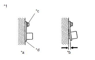
(b) Check the front speed sensor RH installation.
OK:
There is no clearance between the front speed sensor RH and the front steering knuckle RH.
The installation bolt is tightened properly.
Torque
8.5 N*m (87 kgf*cm, 75 in.*lbf)
| NG |
|
|
|
6. |
CHECK FRONT SPEED SENSOR RH (CHECK FOR FOREIGN MATTER) |
(a) Remove the front speed sensor RH.
Click here
(b) Check the front speed sensor RH tip.
OK:
The front speed sensor RH tip is free of scratches, oil, and foreign matter.
NOTICE:
- If there is oil or foreign matter on the front speed sensor RH, clean the front speed sensor RH.
- If the front speed sensor RH is damaged, replace the front speed sensor RH with a new one.
-
Check the front speed sensor RH signal after cleaning or replacement.
Click here
| NG |
|
CLEAN OR REPLACE FRONT SPEED SENSOR RH |
|
|
7. |
CHECK FRONT SPEED SENSOR ROTOR RH (CHECK FOR FOREIGN MATTER) |
(a) Remove the front speed sensor rotor RH (front axle hub sub-assembly RH).
Click here
(b) Check the front speed sensor rotor RH.
OK:
The front speed sensor rotor RH is free of scratches, oil, and foreign matter.
NOTICE:
- If there is oil or foreign matter on the front speed sensor rotor RH, clean the front speed sensor rotor RH.
- If the front speed sensor rotor RH is damaged, replace the front speed sensor rotor RH with a new one.
-
Check the front speed sensor RH signal after cleaning or replacement.
Click here
HINT:
- The front speed sensor rotor RH is incorporated into the front axle hub sub-assembly RH.
- If the front speed sensor rotor RH needs to be replaced, replace it together with the front axle hub sub-assembly RH.
|
Result |
Proceed to |
|---|---|
|
OK (w/o AVS) |
A |
|
OK (w/ AVS) |
B |
|
NG (The front speed sensor rotor RH is damaged.) |
C |
|
NG (There is foreign matter on the front speed sensor rotor RH.) |
D |
| C |
|
REPLACE FRONT AXLE HUB SUB-ASSEMBLY RH Click here
|
| D |
|
CLEAN FRONT SPEED SENSOR ROTOR RH |
| B |
|
|
|
8. |
CHECK HARNESS AND CONNECTOR (BRAKE ACTUATOR ASSEMBLY - FRONT SPEED SENSOR RH) |
(a) Turn the engine switch off.
(b) Make sure that there is no looseness at the locking part and the connecting part of the connectors.
OK:
The connector is securely connected.
(c) Disconnect the A28 skid control ECU (brake actuator assembly) connector.
(d) Disconnect the A59 front speed sensor RH connector.
(e) Check both the connector case and the terminals for deformation and corrosion.
OK:
No deformation or corrosion.
(f) Measure the resistance according to the value(s) in the table below.
Standard Resistance:
|
Tester Connection |
Condition |
Specified Condition |
|---|---|---|
|
A28-21 (FR+) - A59-1 (FR+) |
Always |
Below 1 Ω |
|
A28-26 (FR-) - A59-2 (FR-) |
Always |
Below 1 Ω |
|
A28-21 (FR+) or A59-1 (FR+) - Body ground |
Always |
10 kΩ or higher |
|
A28-26 (FR-) or A59-2 (FR-) - Body ground |
Always |
10 kΩ or higher |
| OK |
|
| NG |
|
REPAIR OR REPLACE HARNESS OR CONNECTOR |
|
9. |
INSPECT FRONT SKID CONTROL SENSOR WIRE RH |
|
(a) Turn the engine switch off. |
|
(b) Make sure that there is no looseness at the locking part and the connecting part of the connectors.
OK:
The connector is securely connected.
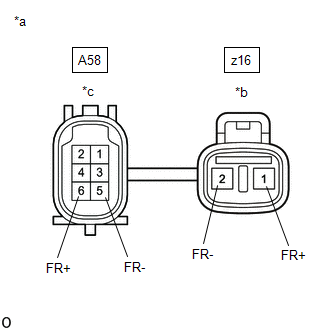
(c) Disconnect the A58 and z16 front skid control sensor wire RH connectors.
(d) Check both the connector case and the terminals for deformation and corrosion.
OK:
No deformation or corrosion.
(e) Measure the resistance according to the value(s) in the table below.
Standard Resistance:
|
Tester Connection |
Condition |
Specified Condition |
|---|---|---|
|
z16-2 (FR-) - A58-5 (FR-) |
Always |
Below 1 Ω |
|
z16-1 (FR+) - A58-6 (FR+) |
Always |
Below 1 Ω |
|
A58-5 (FR-) - z16-1 (FR+) |
Always |
10 kΩ or higher |
|
z16-2 (FR-) or A58-5 (FR-) - Body ground and other terminals |
Always |
10 kΩ or higher |
|
z16-1 (FR+) or A58-6 (FR+) - Body ground and other terminals |
Always |
10 kΩ or higher |
NOTICE:
Check the front speed sensor RH signal after replacement.
Click here
| NG |
|
REPLACE FRONT SKID CONTROL SENSOR WIRE RH |
|
|
10. |
CHECK HARNESS AND CONNECTOR (BRAKE ACTUATOR ASSEMBLY - FRONT SKID CONTROL SENSOR WIRE RH) |
(a) Make sure that there is no looseness at the locking part and the connecting part of the connectors.
OK:
The connector is securely connected.
(b) Disconnect the A28 skid control ECU (brake actuator assembly) connector.
(c) Disconnect the A58 front skid control sensor wire RH connector.
(d) Check both the connector case and the terminals for deformation and corrosion.
OK:
No deformation or corrosion.
(e) Measure the resistance according to the value(s) in the table below.
Standard Resistance:
|
Tester Connection |
Condition |
Specified Condition |
|---|---|---|
|
A28-26 (FR-) - A58-5 (FR-) |
Always |
Below 1 Ω |
|
A28-21 (FR+) - A58-6 (FR+) |
Always |
Below 1 Ω |
|
A28-26 (FR-) or A58-5 (FR-) - Body ground |
Always |
10 kΩ or higher |
|
A28-21 (FR+) or A58-6 (FR+) - Body ground |
Always |
10 kΩ or higher |
| OK |
|
| NG |
|
REPAIR OR REPLACE HARNESS OR CONNECTOR |
|
11. |
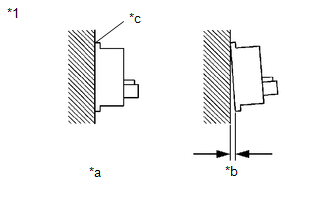
CHECK FRONT SPEED SENSOR LH INSTALLATION |
|
(a) Turn the engine switch off. |
|
(b) Check the front speed sensor LH installation.
OK:
There is no clearance between the front speed sensor LH and the front steering knuckle LH.
The installation bolt is tightened properly.
Torque
8.5 N*m (87 kgf*cm, 75 in.*lbf)
| NG |
|
|
|
12. |
CHECK FRONT SPEED SENSOR LH (CHECK FOR FOREIGN MATTER) |
(a) Remove the front speed sensor LH.
Click here
(b) Check the front speed sensor LH tip.
OK:
The front speed sensor LH tip is free of scratches, oil, and foreign matter.
NOTICE:
- If there is oil or foreign matter on the front speed sensor LH, clean the front speed sensor LH.
- If the front speed sensor LH is damaged, replace the front speed sensor LH with a new one.
-
Check the front speed sensor LH signal after cleaning or replacement.
Click here
| NG |
|
CLEAN OR REPLACE FRONT SPEED SENSOR LH |
|
|
13. |
CHECK FRONT SPEED SENSOR ROTOR LH (CHECK FOR FOREIGN MATTER) |
(a) Remove the front speed sensor rotor LH (front axle hub sub-assembly LH).
Click here
(b) Check the front speed sensor rotor LH.
OK:
The front speed sensor rotor LH is free of scratches, oil, and foreign matter.
NOTICE:
- If there is oil or foreign matter on the front speed sensor rotor LH, clean the front speed sensor rotor LH.
- If the front speed sensor rotor LH is damaged, replace the front speed sensor rotor LH with a new one.
-
Check the front speed sensor LH signal after cleaning or replacement.
Click here
HINT:
- The front speed sensor rotor LH is incorporated into the front axle hub sub-assembly LH.
- If the front speed sensor rotor LH needs to be replaced, replace it together with the front axle hub sub-assembly LH.
|
Result |
Proceed to |
|---|---|
|
OK (w/o AVS) |
A |
|
OK (w/ AVS) |
B |
|
NG (The front speed sensor rotor LH is damaged.) |
C |
|
NG (There is foreign matter on the front speed sensor rotor LH.) |
D |
| C |
|
REPLACE FRONT AXLE HUB SUB-ASSEMBLY LH Click here
|
| D |
|
CLEAN FRONT SPEED SENSOR ROTOR LH |
| B |
|
|
|
14. |
CHECK HARNESS AND CONNECTOR (BRAKE ACTUATOR ASSEMBLY - FRONT SPEED SENSOR LH) |
(a) Turn the engine switch off.
(b) Make sure that there is no looseness at the locking part and the connecting part of the connectors.
OK:
The connector is securely connected.
(c) Disconnect the A28 skid control ECU (brake actuator assembly) connector.
(d) Disconnect the A61 front speed sensor LH connector.
(e) Check both the connector case and the terminals for deformation and corrosion.
OK:
No deformation or corrosion.
(f) Measure the resistance according to the value(s) in the table below.
Standard Resistance:
|
Tester Connection |
Condition |
Specified Condition |
|---|---|---|
|
A28-7 (FL-) - A61-2 (FL-) |
Always |
Below 1 Ω |
|
A28-24 (FL+) - A61-1 (FL+) |
Always |
Below 1 Ω |
|
A28-7 (FL-) or A61-2 (FL-) - Body ground |
Always |
10 kΩ or higher |
|
A28-24 (FL+) or A61-1 (FL+) - Body ground |
Always |
10 kΩ or higher |
| OK |
|
| NG |
|
REPAIR OR REPLACE HARNESS OR CONNECTOR |
|
15. |
INSPECT FRONT SKID CONTROL SENSOR WIRE LH |
|
(a) Turn the engine switch off. |
|
(b) Make sure that there is no looseness at the locking part and the connecting part of the connectors.
OK:
The connector is securely connected.
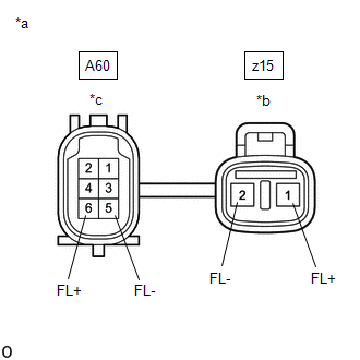
(c) Disconnect the A60 and z15 front skid control sensor wire LH connectors.
(d) Check both the connector case and the terminals for deformation and corrosion.
OK:
No deformation or corrosion.
(e) Measure the resistance according to the value(s) in the table below.
Standard Resistance:
|
Tester Connection |
Condition |
Specified Condition |
|---|---|---|
|
z15-2 (FL-) - A60-5 (FL-) |
Always |
Below 1 Ω |
|
z15-1 (FL+) - A60-6 (FL+) |
Always |
Below 1 Ω |
|
A60-5 (FL-) - z15-1 (FL+) |
Always |
10 kΩ or higher |
|
z15-2 (FL-) or A60-5 (FL-) - Body ground and other terminals |
Always |
10 kΩ or higher |
|
z15-1 (FL+) or A60-6 (FL+) - Body ground and other terminals |
Always |
10 kΩ or higher |
NOTICE:
Check the front speed sensor LH signal after replacement.
Click here
| NG |
|
REPLACE FRONT SKID CONTROL SENSOR WIRE LH |
|
|
16. |
CHECK HARNESS AND CONNECTOR (BRAKE ACTUATOR ASSEMBLY - FRONT SKID CONTROL SENSOR WIRE LH) |
(a) Make sure that there is no looseness at the locking part and the connecting part of the connectors.
OK:
The connector is securely connected.
(b) Disconnect the A28 skid control ECU (brake actuator assembly) connector.
(c) Disconnect the A60 front skid control sensor wire LH connector.
(d) Check both the connector case and the terminals for deformation and corrosion.
OK:
No deformation or corrosion.
(e) Measure the resistance according to the value(s) in the table below.
Standard Resistance:
|
Tester Connection |
Condition |
Specified Condition |
|---|---|---|
|
A28-7 (FL-) - A60-5 (FL-) |
Always |
Below 1 Ω |
|
A28-24 (FL+) - A60-6 (FL+) |
Always |
Below 1 Ω |
|
A28-7 (FL-) or A60-5 (FL-) - Body ground |
Always |
10 kΩ or higher |
|
A28-24 (FL+) or A60-6 (FL+) - Body ground |
Always |
10 kΩ or higher |
| OK |
|
| NG |
|
REPAIR OR REPLACE HARNESS OR CONNECTOR |
|
17. |
CHECK REAR SPEED SENSOR RH INSTALLATION |
|
(a) Turn the engine switch off. |
|
(b) Check the rear speed sensor RH installation.
OK:
There is no clearance between the rear speed sensor RH and the rear axle hub RH.
HINT:
Because the rear axle hub and bearing assembly RH cannot be disassembled, if the rear speed sensor RH needs replacement, replace the rear axle hub and bearing assembly RH.
|
Result |
Proceed to |
|---|---|
|
OK (w/o AVS) |
A |
|
OK (w/ AVS) |
B |
|
NG |
C |
| C |
|
| B |
|
|
|
18. |
INSPECT NO. 1 PARKING BRAKE WIRE ASSEMBLY |
|
(a) Turn the engine switch off. |
|
(b) Make sure that there is no looseness at the locking part and the connecting part of the connectors.
OK:
The connector is securely connected.
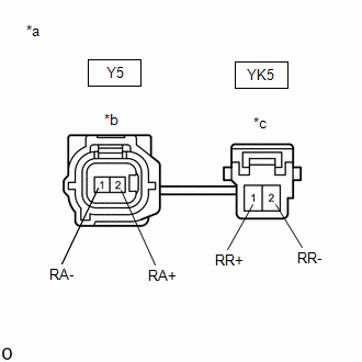
(c) Disconnect the Y5 and YK5 skid control sensor wire RH (No. 1 parking brake wire assembly) connectors.
(d) Check both the connector case and the terminals for deformation and corrosion.
OK:
No deformation or corrosion.
(e) Measure the resistance according to the value(s) in the table below.
Standard Resistance:
|
Tester Connection |
Condition |
Specified Condition |
|---|---|---|
|
Y5-1 (RA-) - YK5-2 (RR-) |
Always |
Below 1 Ω |
|
Y5-2 (RA+) - YK5-1 (RR+) |
Always |
Below 1 Ω |
|
Y5-1 (RA-) - YK5-1 (RR+) |
Always |
10 kΩ or higher |
|
Y5-1 (RA-) or YK5-2 (RR-) - Body ground and other terminals |
Always |
10 kΩ or higher |
|
Y5-2 (RA+) or YK5-1 (RR+) - Body ground and other terminals |
Always |
10 kΩ or higher |
NOTICE:
Check the rear speed sensor RH signal after replacement.
Click here
| NG |
|
REPLACE NO. 1 PARKING BRAKE WIRE ASSEMBLY |
|
|
19. |
CHECK HARNESS AND CONNECTOR (BRAKE ACTUATOR ASSEMBLY - NO. 1 PARKING BRAKE WIRE ASSEMBLY) |
(a) Make sure that there is no looseness at the locking part and the connecting part of the connector.
OK:
The connector is securely connected.
(b) Disconnect the A28 skid control ECU (brake actuator assembly) connector.
(c) Disconnect the YK5 skid control sensor Wire RH (No. 1 parking brake wire assembly) connector.
(d) Check both the connector case and the terminals for deformation and corrosion.
OK:
No deformation or corrosion.
(e) Measure the resistance according to the value(s) in the table below.
Standard Resistance:
|
Tester Connection |
Condition |
Specified Condition |
|---|---|---|
|
A28-37 (RR-) - YK5-2 (RR-) |
Always |
Below 1 Ω |
|
A28-22 (RR+) - YK5-1 (RR+) |
Always |
Below 1 Ω |
|
A28-37 (RR-) or YK5-2 (RR-) - Body ground |
Always |
10 kΩ or higher |
|
A28-22 (RR+) or YK5-1 (RR+) - Body ground |
Always |
10 kΩ or higher |
| OK |
|
| NG |
|
REPAIR OR REPLACE HARNESS OR CONNECTOR |
|
20. |
INSPECT NO. 1 PARKING BRAKE WIRE ASSEMBLY |
|
(a) Turn the engine switch off. |
|
(b) Make sure that there is no looseness at the locking part and the connecting part of the connectors.
OK:
The connector is securely connected.
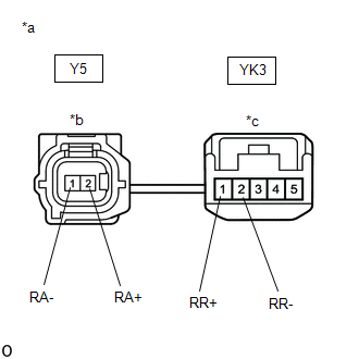
(c) Disconnect the Y5 and YK3 skid control sensor wire RH (No. 1 parking brake wire assembly) connectors.
(d) Check both the connector case and the terminals for deformation and corrosion.
OK:
No deformation or corrosion.
(e) Measure the resistance according to the value(s) in the table below.
Standard Resistance:
|
Tester Connection |
Condition |
Specified Condition |
|---|---|---|
|
Y5-1 (RA-) - YK3-2 (RR-) |
Always |
Below 1 Ω |
|
Y5-2 (RA+) - YK3-1 (RR+) |
Always |
Below 1 Ω |
|
Y5-1 (RA-) - YK3-1 (RR+) |
Always |
10 kΩ or higher |
|
Y5-1 (RA-) or YK3-2 (RR-) - Body ground and other terminals |
Always |
10 kΩ or higher |
|
Y5-2 (RA+) or YK3-1 (RR+) - Body ground and other terminals |
Always |
10 kΩ or higher |
NOTICE:
Check the rear speed sensor RH signal after replacement.
Click here
| NG |
|
REPLACE NO. 1 PARKING BRAKE WIRE ASSEMBLY |
|
|
21. |
CHECK HARNESS AND CONNECTOR (BRAKE ACTUATOR ASSEMBLY - NO. 1 PARKING BRAKE WIRE ASSEMBLY) |
(a) Make sure that there is no looseness at the locking part and the connecting part of the connector.
OK:
The connector is securely connected.
(b) Disconnect the A28 skid control ECU (brake actuator assembly) connector.
(c) Disconnect the YK3 skid control sensor Wire RH (No. 1 parking brake wire assembly) connector.
(d) Check both the connector case and the terminals for deformation and corrosion.
OK:
No deformation or corrosion.
(e) Measure the resistance according to the value(s) in the table below.
Standard Resistance:
|
Tester Connection |
Condition |
Specified Condition |
|---|---|---|
|
A28-37 (RR-) - YK3-2 (RR-) |
Always |
Below 1 Ω |
|
A28-22 (RR+) - YK3-1 (RR+) |
Always |
Below 1 Ω |
|
A28-37 (RR-) or YK3-2 (RR-) - Body ground |
Always |
10 kΩ or higher |
|
A28-22 (RR+) or YK3-1 (RR+) - Body ground |
Always |
10 kΩ or higher |
| OK |
|
| NG |
|
REPAIR OR REPLACE HARNESS OR CONNECTOR |
|
22. |
CHECK REAR SPEED SENSOR LH INSTALLATION |
|
(a) Turn the engine switch off. |
|
(b) Check the rear speed sensor LH installation.
OK:
There is no clearance between the rear speed sensor LH and the rear axle hub LH.
HINT:
Because the rear axle hub and bearing assembly LH cannot be disassembled, if the rear speed sensor LH needs replacement, replace the rear axle hub and bearing assembly LH.
|
Result |
Proceed to |
|---|---|
|
OK (w/o AVS) |
A |
|
OK (w/ AVS) |
B |
|
NG |
C |
| C |
|
| B |
|
|
|
23. |
INSPECT NO. 2 PARKING BRAKE WIRE ASSEMBLY |
|
(a) Turn the engine switch off. |
|
(b) Make sure that there is no looseness at the locking part and the connecting part of the connectors.
OK:
The connector is securely connected.
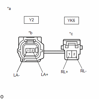
(c) Disconnect the Y2 and YK6 skid control sensor wire LH (No. 2 parking brake wire assembly) connectors.
(d) Check both the connector case and the terminals for deformation and corrosion.
OK:
No deformation or corrosion.
(e) Measure the resistance according to the value(s) in the table below.
Standard Resistance:
|
Tester Connection |
Condition |
Specified Condition |
|---|---|---|
|
Y2-1 (LA-) - YK6-2 (RL-) |
Always |
Below 1 Ω |
|
Y2-2 (LA+) - YK6-1 (RL+) |
Always |
Below 1 Ω |
|
Y2-1 (LA-) - YK6-1 (RL+) |
Always |
10 kΩ or higher |
|
Y2-1 (LA-) or YK6-2 (RL-) - Body ground and other terminals |
Always |
10 kΩ or higher |
|
Y2-2 (LA+) or YK6-1 (RL+) - Body ground and other terminals |
Always |
10 kΩ or higher |
NOTICE:
Check the rear speed sensor LH signal after replacement.
Click here
| NG |
|
REPLACE NO. 2 PARKING BRAKE WIRE ASSEMBLY |
|
|
24. |
CHECK HARNESS AND CONNECTOR (BRAKE ACTUATOR ASSEMBLY - NO. 2 PARKING BRAKE WIRE ASSEMBLY) |
(a) Make sure that there is no looseness at the locking part and the connecting part of the connector.
OK:
The connector is securely connected.
(b) Disconnect the A28 skid control ECU (brake actuator assembly) connector.
(c) Disconnect the YK6 skid control sensor Wire LH (No. 2 parking brake wire assembly) connector.
(d) Check both the connector case and the terminals for deformation and corrosion.
OK:
No deformation or corrosion.
(e) Measure the resistance according to the value(s) in the table below.
Standard Resistance:
|
Tester Connection |
Condition |
Specified Condition |
|---|---|---|
|
A28-23 (RL-) - YK6-2 (RL-) |
Always |
Below 1 Ω |
|
A28-39 (RL+) - YK6-1 (RL+) |
Always |
Below 1 Ω |
|
A28-23 (RL-) or YK6-2 (RL-) - Body ground |
Always |
10 kΩ or higher |
|
A28-39 (RL+) or YK6-1 (RL+) - Body ground |
Always |
10 kΩ or higher |
| OK |
|
| NG |
|
REPAIR OR REPLACE HARNESS OR CONNECTOR |
|
25. |
INSPECT NO. 2 PARKING BRAKE WIRE ASSEMBLY |
|
(a) Turn the engine switch off. |
|
(b) Make sure that there is no looseness at the locking part and the connecting part of the connectors.
OK:
The connector is securely connected.
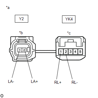
(c) Disconnect the Y2 and YK4 skid control sensor wire LH (No. 2 parking brake wire assembly) connectors.
(d) Check both the connector case and the terminals for deformation and corrosion.
OK:
No deformation or corrosion.
(e) Measure the resistance according to the value(s) in the table below.
Standard Resistance:
|
Tester Connection |
Condition |
Specified Condition |
|---|---|---|
|
Y2-1 (LA-) - YK4-2 (RL-) |
Always |
Below 1 Ω |
|
Y2-2 (LA+) - YK4-1 (RL+) |
Always |
Below 1 Ω |
|
Y2-1 (LA-) - YK4-1 (RL+) |
Always |
10 kΩ or higher |
|
Y2-1 (LA-) or YK4-2 (RL-) - Body ground and other terminals |
Always |
10 kΩ or higher |
|
Y2-2 (LA+) or YK4-1 (RL+) - Body ground and other terminals |
Always |
10 kΩ or higher |
NOTICE:
Check the rear speed sensor LH signal after replacement.
Click here
| NG |
|
REPLACE NO. 2 PARKING BRAKE WIRE ASSEMBLY |
|
|
26. |
CHECK HARNESS AND CONNECTOR (BRAKE ACTUATOR ASSEMBLY - NO. 2 PARKING BRAKE WIRE ASSEMBLY) |
(a) Make sure that there is no looseness at the locking part and the connecting part of the connector.
OK:
The connector is securely connected.
(b) Disconnect the A28 skid control ECU (brake actuator assembly) connector.
(c) Disconnect the YK4 skid control sensor Wire LH (No. 2 parking brake wire assembly) connector.
(d) Check both the connector case and the terminals for deformation and corrosion.
OK:
No deformation or corrosion.
(e) Measure the resistance according to the value(s) in the table below.
Standard Resistance:
|
Tester Connection |
Condition |
Specified Condition |
|---|---|---|
|
A28-23 (RL-) - YK4-2 (RL-) |
Always |
Below 1 Ω |
|
A28-39 (RL+) - YK4-1 (RL+) |
Always |
Below 1 Ω |
|
A28-23 (RL-) or YK4-2 (RL-) - Body ground |
Always |
10 kΩ or higher |
|
A28-39 (RL+) or YK4-1 (RL+) - Body ground |
Always |
10 kΩ or higher |
| OK |
|
| NG |
|
REPAIR OR REPLACE HARNESS OR CONNECTOR |
|
|
|