| Last Modified: 09-10-2025 | 6.11:8.1.0 | Doc ID: RM100000001AZ85 |
| Model Year Start: 2019 | Model: Avalon | Prod Date Range: [04/2018 - 08/2021] |
| Title: BRAKE CONTROL / DYNAMIC CONTROL SYSTEMS: ELECTRONICALLY CONTROLLED BRAKE SYSTEM (for Gasoline Model): C1432; Steering Angle Sensor Power Source Voltage; 2019 - 2021 MY Avalon [04/2018 - 08/2021] | ||
|
DTC |
C1432 |
Steering Angle Sensor Power Source Voltage |
DESCRIPTION
This DTC is stored when the skid control ECU (brake actuator assembly) receives a +B line open signal from the steering angle sensor.
|
DTC No. |
Detection Item |
DTC Detection Condition |
Trouble Area |
|---|---|---|---|
|
C1432 |
Steering Angle Sensor Power Source Voltage |
With the +BS terminal voltage between 9.6 and 16.5 V, a steering angle sensor power supply circuit malfunction signal is received from the steering angle sensor. |
|
WIRING DIAGRAM
Refer to DTC C1231.
Click here
![2019 - 2021 MY Avalon [04/2018 - 08/2021]; BRAKE CONTROL / DYNAMIC CONTROL SYSTEMS: ELECTRONICALLY CONTROLLED BRAKE SYSTEM (for Gasoline Model): C1231; Steering Angle Sensor Circuit](/t3Portal/stylegraphics/info.gif)
CAUTION / NOTICE / HINT
NOTICE:
Inspect the fuses for circuits related to this system before performing the following procedure.
PROCEDURE
PROCEDURE
|
1. |
CHECK HARNESS AND CONNECTOR (POWER SOURCE TERMINAL) |
|
(a) Remove the steering wheel and column cover. |
|
(b) Make sure that there is no looseness at the locking part and the connecting part of the connector.
OK:
The connector is securely connected.
(c) Disconnect the G48 steering angle sensor connector.
(d) Check both the connector case and the terminals for deformation and corrosion.
OK:
No deformation or corrosion.
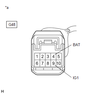
(e) Measure the voltage according to the value(s) in the table below.
Standard Voltage:
|
Tester Connection |
Condition |
Specified Condition |
|---|---|---|
|
G48-4 (BAT) - Body ground |
Always |
11 to 14 V |
|
G48-9 (IG1) - Body ground |
Engine switch on (IG) |
11 to 14 V |
| NG |

|
REPAIR OR REPLACE HARNESS OR CONNECTOR (POWER SOURCE CIRCUIT) |
|

|
2. |
CHECK HARNESS AND CONNECTOR (GROUND TERMINAL) |
|
(a) Turn the engine switch off. |
|
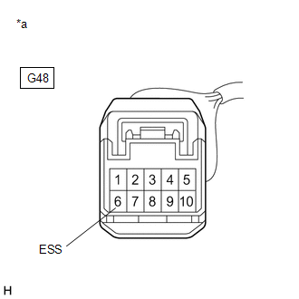
(b) Measure the resistance according to the value(s) in the table below.
NOTICE:
Before measuring the resistance of the steering angle sensor, turn the engine switch off and leave the vehicle for 1 minute or more without operating the key or switches, or opening or closing the doors.
Standard Resistance:
|
Tester Connection |
Condition |
Specified Condition |
|---|---|---|
|
G48-6 (ESS) - Body ground |
1 minute after engine switch off |
Below 1 Ω |
| OK |
|
| NG |
|
REPAIR OR REPLACE HARNESS OR CONNECTOR (GROUND CIRCUIT) |
|
|
|