| Last Modified: 08-21-2023 | 6.11:8.1.0 | Doc ID: RM100000001AYW7 |
| Model Year Start: 2019 | Model: Avalon | Prod Date Range: [04/2018 - ] |
| Title: 2GR-FKS (ENGINE MECHANICAL): ENGINE UNIT: INSTALLATION; 2019 - 2022 MY Avalon [04/2018 - ] | ||
INSTALLATION
PROCEDURE
1. INSTALL ENGINE COVER BRACKET
(a) Install the engine cover bracket to the cylinder head cover sub-assembly LH with the bolt.
Torque:
10 N·m {102 kgf·cm, 7 ft·lbf}
2. INSTALL WATER FILLER BRACKET
|
(a) Temporarily install the water filler bracket to the camshaft housing sub-assembly LH with the 2 bolts. |
|
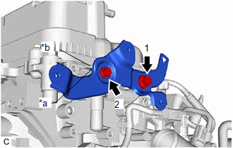
(b) Fully tighten the 2 bolts in the order shown in the illustration.
Torque:
8.0 N·m {82 kgf·cm, 71 in·lbf}
NOTICE:
Make sure that the stopper of the water filler bracket is pressed against the protrusion of the camshaft housing sub-assembly LH when fully tightening the 2 bolts.
3. INSTALL WIRE HARNESS CLAMP BRACKET
(a) Install the wire harness clamp bracket to the camshaft housing sub-assembly with the bolt.
Torque:
30 N·m {306 kgf·cm, 22 ft·lbf}
(b) Install the wire harness clamp bracket to the camshaft housing sub-assembly LH with the bolt.
Torque:
30 N·m {306 kgf·cm, 22 ft·lbf}
4. INSTALL DRIVE SHAFT BEARING BRACKET
(a) Install the drive shaft bearing bracket to the cylinder block sub-assembly with the 3 bolts.
Torque:
63.7 N·m {650 kgf·cm, 47 ft·lbf}
NOTICE:
Make sure that there is no oil on the threads of the bolts.
5. INSTALL ENGINE OIL LEVEL DIPSTICK GUIDE
(a) Install a new engine oil level dipstick guide O-ring to the engine oil level dipstick guide.
(b) Apply a light coat of engine oil to the engine oil level dipstick guide O-ring.
(c) Insert the engine oil level dipstick guide end into the oil pan sub-assembly.
(d) Install the engine oil level dipstick guide to the camshaft housing sub-assembly LH with the bolt.
Torque:
21 N·m {214 kgf·cm, 15 ft·lbf}
(e) Install the engine oil level dipstick to the engine oil level dipstick guide.
6. INSTALL WATER PUMP PULLEY
Click here
![2019 - 2022 MY Avalon [04/2018 - ]; 2GR-FKS (COOLING): WATER PUMP: INSTALLATION+](/t3Portal/stylegraphics/info.gif)
7. INSTALL V-RIBBED BELT TENSIONER ASSEMBLY
(a) Install the V-ribbed belt tensioner assembly with the 2 bolts.
Torque:
43 N·m {438 kgf·cm, 32 ft·lbf}
8. INSTALL NO. 2 IDLER PULLEY SUB-ASSEMBLY
Click here
9. INSTALL NO. 1 COMPRESSOR MOUNTING BRACKET
|
(a) Temporarily install the No. 1 compressor mounting bracket to the cylinder block sub-assembly with the 2 bolts. |
|
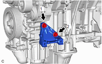
(b) Fully tighten the 2 bolts in the order shown in the illustration.
Torque:
43 N·m {438 kgf·cm, 32 ft·lbf}
10. INSTALL COMPRESSOR ASSEMBLY WITH MAGNETIC CLUTCH
Click here
11. INSTALL GENERATOR ASSEMBLY
Click here
12. INSTALL V-RIBBED BELT
Click here
13. INSTALL NO. 2 VENTILATION HOSE
(a) Install the No. 2 ventilation hose to the cylinder head cover sub-assembly and slide the clip to secure it.
14. INSTALL VENTILATION HOSE
(a) Install the ventilation hose to the PCV valve (ventilation valve sub-assembly) and slide the clip to secure it.
15. INSTALL NO. 2 WATER BY-PASS HOSE
(a) Install the No. 2 water by-pass hose to the water outlet and slide the clip to secure it.
16. INSTALL NO. 3 WATER BY-PASS HOSE
(a) Install the No. 3 water by-pass hose to the water inlet pipe and slide the clip to secure it.
17. INSTALL VACUUM PUMP ASSEMBLY
Click here
18. INSTALL IGNITION COIL ASSEMBLY
Click here
19. INSTALL SENSOR WIRE
(a) Engage the 2 clamps and install the sensor wire with the bolt.
Torque:
10 N·m {102 kgf·cm, 7 ft·lbf}
20. INSTALL KNOCK CONTROL SENSOR
Click here
|
|
|