- Replacement of throttle body with motor assembly
- Cleaning the deposits from the throttle body with motor assembly
| Last Modified: 08-21-2023 | 6.11:8.1.0 | Doc ID: RM100000001AYSQ |
| Model Year Start: 2019 | Model: Avalon | Prod Date Range: [04/2018 - ] |
| Title: 2GR-FKS (ENGINE CONTROL): CAMSHAFT POSITION SENSOR: REMOVAL; 2019 - 2022 MY Avalon [04/2018 - ] | ||
REMOVAL
CAUTION / NOTICE / HINT
The necessary procedures (adjustment, calibration, initialization or registration) that must be performed after parts are removed and installed, or replaced during VVT sensor removal/installation are shown below.
Necessary Procedures After Parts Removed/Installed/Replaced
|
Replaced Part or Performed Procedure |
Necessary Procedure |
Effect/Inoperative Function when Necessary Procedure not Performed |
Link |
|---|---|---|---|
|
|
Inspection after repair |
|
PROCEDURE
1. REMOVE INTAKE AIR SURGE TANK ASSEMBLY
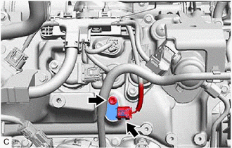
2. REMOVE VVT SENSOR (for Intake Side of Bank 1)
|
(a) Disconnect the VVT sensor connector. |
|
(b) Remove the bolt and VVT sensor from the cylinder head cover sub-assembly.
NOTICE:
If the VVT sensor has been struck or dropped, replace it.
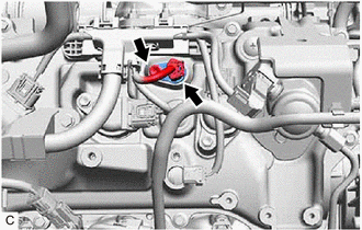
3. REMOVE VVT SENSOR (for Exhaust Side of Bank 1)
|
(a) Disconnect the VVT sensor connector. |
|
(b) Remove the bolt and VVT sensor from the cylinder head cover sub-assembly.
NOTICE:
If the VVT sensor has been struck or dropped, replace it.
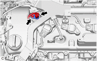
4. REMOVE VVT SENSOR (for Intake Side of Bank 2)
|
(a) Disconnect the VVT sensor connector. |
|
(b) Remove the bolt and VVT sensor from the cylinder head cover sub-assembly LH.
NOTICE:
If the VVT sensor has been struck or dropped, replace it.
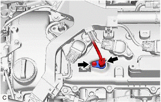
5. REMOVE VVT SENSOR (for Exhaust Side of Bank 2)
|
(a) Disconnect the VVT sensor connector. |
|
(b) Remove the bolt and VVT sensor from the cylinder head cover sub-assembly LH.
NOTICE:
If the VVT sensor has been struck or dropped, replace it.
|
|
|
![2019 MY Avalon [04/2018 - 08/2019]; 2GR-FKS (ENGINE CONTROL): SFI SYSTEM: INITIALIZATION](/t3Portal/stylegraphics/info.gif)


