| Last Modified: 08-21-2023 | 6.11:8.1.0 | Doc ID: RM100000001AYSN |
| Model Year Start: 2019 | Model: Avalon | Prod Date Range: [04/2018 - ] |
| Title: 2GR-FKS (ENGINE CONTROL): MASS AIR FLOW METER: ON-VEHICLE INSPECTION; 2019 - 2022 MY Avalon [04/2018 - ] | ||
ON-VEHICLE INSPECTION
PROCEDURE
1. INSPECT MASS AIR FLOW METER SUB-ASSEMBLY
HINT:
Perform "Inspection After Repair" after replacing the mass air flow meter sub-assembly.
Click here
![2019 MY Avalon [04/2018 - 08/2019]; 2GR-FKS (ENGINE CONTROL): SFI SYSTEM: INITIALIZATION](/t3Portal/stylegraphics/info.gif)
(a) Read the value of Data List item "Mass Air Flow Sensor" using the Techstream.
NOTICE:
Perform the inspection of the mass air flow meter sub-assembly while it is installed to the air cleaner cap sub-assembly (installed to the vehicle).
(1) Check and ensure the following conditions:
- Turn off all electrical loads, such as the air conditioning, etc.
- Check that the coolant temperature is 75°C (167°F) or more.
- Put the shift lever in the N position.
(2) Connect the Techstream to the DLC3.
(3) Start the engine.
(4) Turn the Techstream on.
(5) Enter the following menus: Powertrain / Engine / Data List / Mass Air Flow Sensor.
Powertrain > Engine > Data List
|
Tester Display |
|---|
|
Mass Air Flow Sensor |
(6) According to the display on the Techstream, read the Data List when the engine is running.
Standard Condition:
|
Techstream Display |
Condition |
Specified Condition |
|---|---|---|
|
Mass Air Flow Sensor |
Idling (engine warmed up) |
2.6 to 3.7 gm/sec |
|
2000 rpm (without load) |
5.4 to 9.6 gm/sec |
|
|
3000 rpm (without load) |
10.6 to 15.8 gm/sec |
If the result is not as specified, clean the mass air flow meter sub-assembly.
If the result is within the specified range, check the intake air temperature sensor (thermistor) resistance.
Click here
2. CLEAN MASS AIR FLOW METER SUB-ASSEMBLY
NOTICE:
If the mass air flow meter sub-assembly is removed and installed 10 times or more, the thread of the hole of the mass air flow meter sub-assembly may be damaged. Therefore, do not loosen the screws of the mass air flow meter sub-assembly.
(a) Remove the air cleaner cap sub-assembly.
(b) Clean the mass air flow meter sub-assembly.
NOTICE:
- Do not contact the mass air flow meter sub-assembly with the nozzle of the air blow gun.
- Do not insert the nozzle of the air blow gun into the airflow hole.
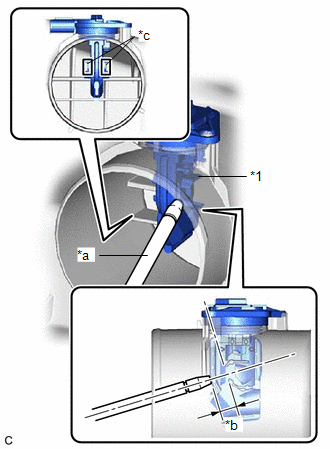
|
*1 |
Mass Air Flow Meter Sub-assembly |
|
*a |
Air Blow Gun |
|
*b |
10 mm (0.394 in.) |
|
*c |
Airflow Hole |
|
(1) Using an air blow gun, clean the hole of the mass air flow meter sub-assembly by applying approximately 10 intermittent bursts of air to the airflow hole at a pressure of approximately 392 to 981 kPa (4.0 to 10.0 kgf/cm2, 57 to 142 psi). HINT: Apply 5 intermittent bursts of air to the airflow hole at 2 locations. |
|
(c) Install the air cleaner cap sub-assembly.
3. PERFORM INITIALIZATION
(a) Perform "Inspection After Repair" after replacing the mass air flow meter sub-assembly.
Click here
|
|
|