| Last Modified: 08-21-2023 | 6.11:8.1.0 | Doc ID: RM100000001AYCO |
| Model Year Start: 2019 | Model: Avalon | Prod Date Range: [04/2018 - ] |
| Title: LIGHTING (EXT): LIGHTING SYSTEM (for Gasoline Model without Cornering Light): Hazard Warning Switch Circuit; 2019 - 2022 MY Avalon [04/2018 - ] | ||
|
Hazard Warning Switch Circuit |
DESCRIPTION
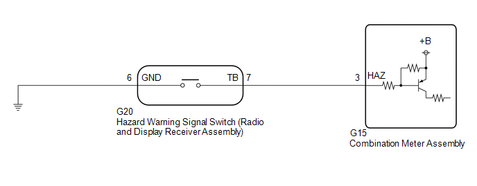
The combination meter assembly receives the hazard warning signal switch (radio and display receiver assembly) on signal and controls the operation of the hazard warning lights.
WIRING DIAGRAM
CAUTION / NOTICE / HINT
NOTICE:
When replacing the combination meter assembly, always replace it with a new one. If a combination meter assembly which was installed to another vehicle is used, the information stored in it will not match the information from the vehicle and a DTC may be stored.
PROCEDURE
|
1. |
READ VALUE USING TECHSTREAM |
(a) Connect the Techstream to the DLC3.
(b) Turn the engine switch on (IG).
(c) Turn the Techstream on.
(d) Enter the following menus: Body Electrical / Combination Meter / Data List.
(e) Read the Data List according to the display on the Techstream.
Body Electrical > Combination Meter > Data List
|
Tester Display |
Measurement Item |
Range |
Normal Condition |
Diagnostic Note |
|---|---|---|---|---|
|
Hazard Flasher Switch |
Hazard warning signal switch signal |
OFF or ON |
OFF: Hazard warning signal switch off ON: Hazard warning signal switch on |
- |
Body Electrical > Combination Meter > Data List
|
Tester Display |
|---|
|
Hazard Flasher Switch |
OK:
Normal conditions listed above are displayed.
| OK |

|
PROCEED TO NEXT SUSPECTED AREA SHOWN IN PROBLEM SYMPTOMS TABLE
|
|

|
2. |
INSPECT HAZARD WARNING SIGNAL SWITCH (RADIO AND DISPLAY RECEIVER ASSEMBLY) |
(a) Remove the hazard warning signal switch (radio and display receiver assembly).
Click here
![2019 - 2022 MY Avalon Avalon HV [04/2018 - ]; LIGHTING (EXT): HAZARD WARNING SWITCH: REMOVAL](/t3Portal/stylegraphics/info.gif)
(b) Inspect the hazard warning signal switch (radio and display receiver assembly).
Click here
| NG |
|
REPLACE HAZARD WARNING SIGNAL SWITCH (RADIO AND DISPLAY RECEIVER ASSEMBLY) |
|
|
3. |
CHECK HARNESS AND CONNECTOR (HAZARD WARNING SIGNAL SWITCH (RADIO AND DISPLAY RECEIVER ASSEMBLY) - COMBINATION METER ASSEMBLY AND BODY GROUND) |
(a) Disconnect the G15 combination meter assembly connector.
(b) Measure the resistance according to the value(s) in the table below.
Standard Resistance:
|
Tester Connection |
Condition |
Specified Condition |
|---|---|---|
|
G20-7 (TB) - G15-3 (HAZ) |
Always |
Below 1 Ω |
|
G20-7 (TB) or G15-3 (HAZ) - Body ground |
Always |
10 kΩ or higher |
|
G20-6 (GND) - Body ground |
Always |
Below 1 Ω |
| OK |
|
REPLACE COMBINATION METER ASSEMBLY
|
| NG |
|
REPAIR OR REPLACE HARNESS OR CONNECTOR |
|
|
|