| Last Modified: 08-21-2023 | 6.11:8.1.0 | Doc ID: RM100000001AYBP |
| Model Year Start: 2019 | Model: Avalon HV | Prod Date Range: [04/2018 - 08/2019] |
| Title: HEATING / AIR CONDITIONING: AIR CONDITIONING UNIT (for HV Model): REASSEMBLY; 2019 MY Avalon HV [04/2018 - 08/2019] | ||
REASSEMBLY
PROCEDURE
1. INSTALL NO. 1 COOLER THERMISTOR
Click here
![2019 - 2020 MY Avalon Avalon HV [04/2018 - 08/2020]; HEATING / AIR CONDITIONING: FRONT EVAPORATOR TEMPERATURE SENSOR: INSTALLATION+](/t3Portal/stylegraphics/info.gif)
2. INSTALL NO. 1 COOLER EVAPORATOR SUB-ASSEMBLY
|
(a) Install the No. 1 cooler evaporator sub-assembly with No. 1 cooler thermistor to the upper heater case. |
|
(b) Engage the clamp.
(c) Engage the 10 claws to install the upper heater case with No. 1 cooler evaporator sub-assembly to the lower heater case.
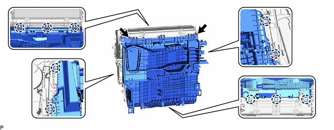
(d) Install the 2 screws.
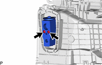
3. INSTALL COOLER EXPANSION VALVE
(a) Sufficiently apply compressor oil to 2 new O-rings and the fitting surfaces of the No. 1 cooler evaporator sub-assembly.
Compressor Oil:
ND-OIL 11 or equivalent
(b) Install the 2 O-rings to the No. 1 cooler evaporator sub-assembly.
NOTICE:
Keep the O-rings and O-ring fitting surfaces free of foreign matter.
|
(c) Using a 4 mm hexagon socket wrench, install the cooler expansion valve with the 2 hexagon bolts. Torque: 3.5 N·m {36 kgf·cm, 31 in·lbf} |
|
4. INSTALL COOLING UNIT PARTS
|
(a) Install the cooling unit parts. |
|
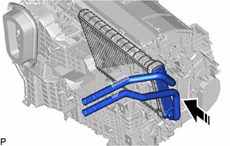
5. INSTALL HEATER RADIATOR UNIT SUB-ASSEMBLY

|
Install in this Direction |
(a) Install the heater radiator unit sub-assembly as shown in the illustration.
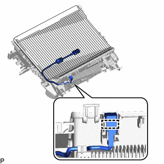
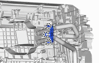
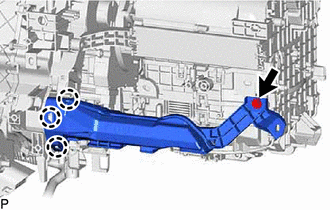
6. INSTALL HEATER CLAMP
|
(a) Engage the 3 claws to install the heater clamp. |
|
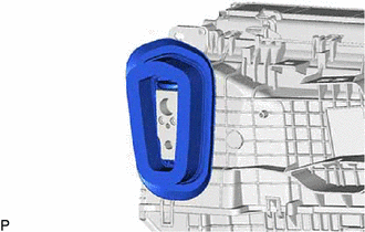
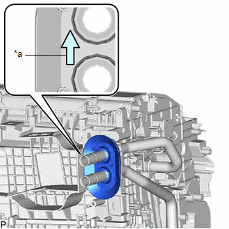
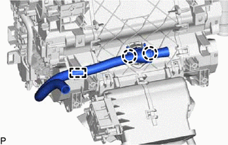
7. INSTALL HEATER PIPE GROMMET
|
(a) Install the heater pipe grommet as shown in the illustration. NOTICE: Install the heater pipe grommet with the arrow facing up. |
|
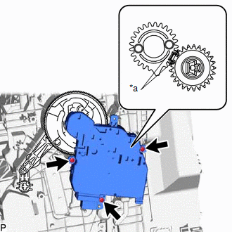
8. INSTALL NO. 3 AIR CONDITIONING RADIATOR DAMPER SERVO SUB-ASSEMBLY
|
(a) Insert the 3 links of the air conditioning radiator assembly into the grooves of the No. 3 air conditioning radiator damper servo sub-assembly as shown in the illustration. |
|
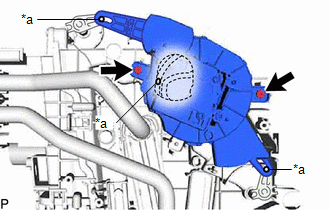
(b) Install the No. 3 air conditioning radiator damper servo sub-assembly with the 2 screws.
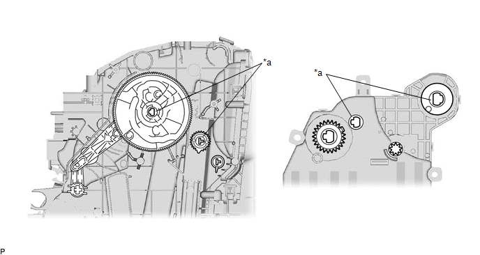
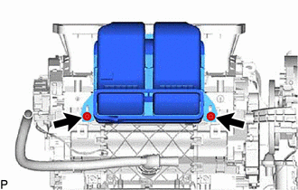
9. INSTALL NO. 2 AIR CONDITIONING RADIATOR DAMPER SERVO SUB-ASSEMBLY
|
(a) Using the reference points, install the No. 2 air conditioning radiator damper servo sub-assembly with the 2 screws. |
|
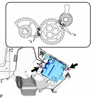
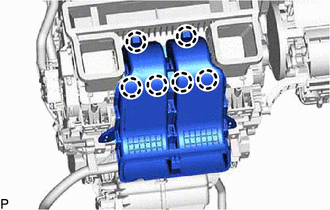
10. INSTALL NO. 1 AIR CONDITIONING RADIATOR DAMPER SERVO SUB-ASSEMBLY
(a) Align each gear on the air conditioning radiator assembly as shown in the illustration, and then check that the gears of the No. 1 air conditioning radiator damper servo sub-assembly are aligned as shown in the illustration.
|
*a |
Reference Point |
- |
- |
|
(b) Using the reference points, install the No. 1 air conditioning radiator damper servo sub-assembly with the 3 screws. |
|
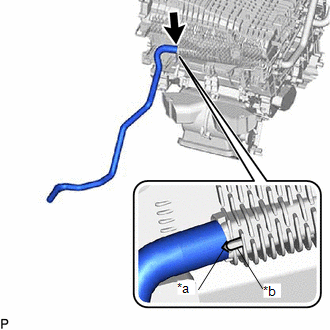
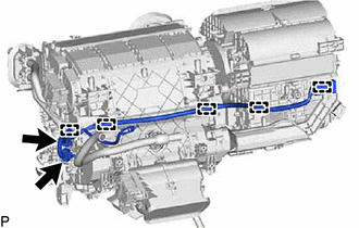
11. INSTALL DRAIN COOLER HOSE
|
(a) Align the hose notch with the rib as shown in the illustration and install the drain cooler hose. |
|
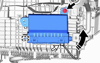
12. INSTALL QUICK HEATER ASSEMBLY
|
|
Install in this Direction |
(a) Install the quick heater assembly as shown in the illustration.
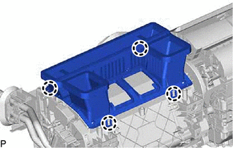
13. INSTALL NO. 2 HEATER COVER
|
(a) Engage the claw and 2 guides. |
|
(b) Install the No. 2 heater cover with the screw.
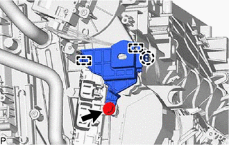
14. INSTALL AIR CONDITIONING HARNESS ASSEMBLY
|
(a) Engage each clamp. |
|
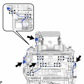
(b) Connect each connector to install the air conditioning harness assembly.
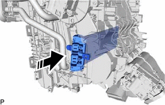
15. INSTALL AIR CONDITIONING AMPLIFIER ASSEMBLY
(a) Engage the guide to temporarily install the air conditioning amplifier assembly as shown in the illustration.
|
|
Install in this Direction |
(b) Install the air conditioning amplifier assembly with the screw.
(c) Connect the connector.
16. INSTALL BLOWER ASSEMBLY
Click here
17. INSTALL ASPIRATOR
|
(a) Engage the 2 claws and guide to install the aspirator. |
|
18. INSTALL NO. 2 AIR DUCT
|
(a) Engage the 3 claws to temporarily install a new No. 2 air duct. |
|
(b) Install the No. 2 air duct with the screw.
19. INSTALL NO. 2 INSTRUMENT PANEL WIRE
|
(a) Engage each clamp. |
|
(b) Connect the 2 connectors to install the No. 2 instrument panel wire.
20. INSTALL NO. 2 AIR DUCT SUB-ASSEMBLY
|
(a) Engage the 4 claws to install the No. 2 air duct sub-assembly. |
|
21. INSTALL NO. 4 HEATER TO REGISTER DUCT SUB-ASSEMBLY
|
(a) Engage the 6 claws. |
|
|
(b) Install the No. 4 heater to register duct sub-assembly with the 2 screws. |
|
|
|
|