| Last Modified: 08-21-2023 | 6.11:8.1.0 | Doc ID: RM100000001AY0W |
| Model Year Start: 2019 | Model: Avalon HV | Prod Date Range: [04/2018 - 08/2021] |
| Title: INTERIOR PANELS / TRIM: INSTRUMENT PANEL SAFETY PAD: REMOVAL; 2019 - 2021 MY Avalon Avalon HV [04/2018 - 08/2021] | ||
REMOVAL
CAUTION / NOTICE / HINT
The necessary procedures (adjustment, calibration, initialization or registration) that must be performed after parts are removed and installed, or replaced during instrument panel safety pad removal/installation are shown below.
Necessary Procedure After Parts Removed/Installed/Replaced (for Gasoline Model)
|
Replaced Part or Performed Procedure |
Necessary Procedure |
Effect/Inoperative Function When Necessary Procedures are not Performed |
Link |
|---|---|---|---|
|
*: When performing learning using the Techstream.
Click here
|
|||
|
Disconnect cable from negative (-) battery terminal |
Perform steering sensor zero point calibration |
Lane Departure Alert System (w/ Steering Control) |
|
|
Pre-collision System |
|||
|
Intelligent Clearance Sonar System* |
|||
|
Lighting System (for Gasoline Model with Cornering Light) |
|||
|
Memorize steering angle neutral point |
Parking Assist Monitor System |
|
|
|
Panoramic View Monitor System |
|
||
Necessary Procedure After Parts Removed/Installed/Replaced (for HV Model)
|
Replaced Part or Performed Procedure |
Necessary Procedure |
Effect/Inoperative Function When Necessary Procedures are not Performed |
Link |
|---|---|---|---|
|
*: When performing learning using the Techstream.
Click here
|
|||
|
Disconnect cable from negative (-) auxiliary battery terminal |
Perform steering sensor zero point calibration |
Lane Departure Alert System (w/ Steering Control) |
|
|
Pre-collision System |
|||
|
Intelligent Clearance Sonar System* |
|||
|
Lighting System (for HV Model with Cornering Light) |
|||
|
Memorize steering angle neutral point |
Parking Assist Monitor System |
|
|
|
Panoramic View Monitor System |
|
||
CAUTION:
Be sure to read Precaution thoroughly before servicing.
for Gasoline Model: Click here
![2019 - 2020 MY Avalon [04/2018 - 08/2020]; SUPPLEMENTAL RESTRAINT SYSTEMS: AIRBAG SYSTEM (for Gasoline Model): PRECAUTION](/t3Portal/stylegraphics/info.gif)
for HV Model: Click here
PROCEDURE
1. PRECAUTION
Click here
NOTICE:
After turning the engine switch (for Gasoline Model) or power switch (for HV Model) off, waiting time may be required before disconnecting the cable from the negative (-) auxiliary battery terminal. Therefore, make sure to read the disconnecting the cable from the negative (-) auxiliary battery terminal notices before proceeding with work.
Click here
2. CHANGE POWER TILT AND POWER TELESCOPIC STEERING COLUMN SYSTEM SETTINGS (for Power Tilt and Power Telescopic Steering Column)
Click here
3. REMOVE CONSOLE ASSEMBLY
Click here
4. REMOVE FRONT DOOR SCUFF PLATE LH
Click here
5. REMOVE COWL SIDE TRIM SUB-ASSEMBLY LH
Click here
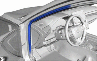
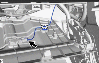
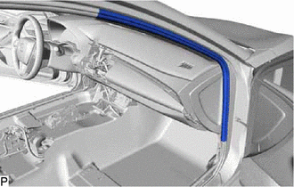
6. DISCONNECT FRONT DOOR OPENING TRIM WEATHERSTRIP LH
|
(a) Disconnect the front door opening trim weatherstrip LH. |
|
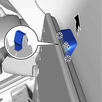
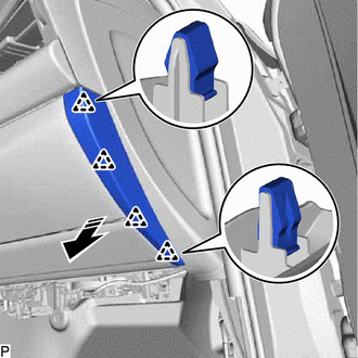
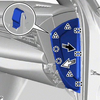
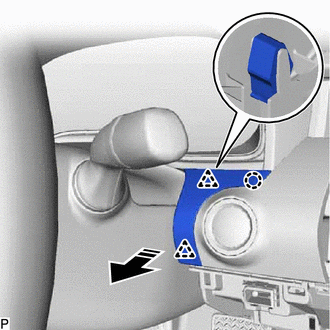
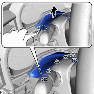
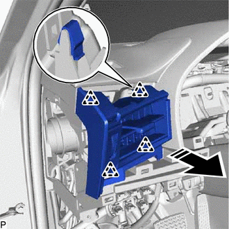
7. REMOVE INSTRUMENT SIDE PANEL LH
(a) Pull the instrument side panel LH in the direction indicated by the arrow (1) shown in the illustration to disengage the claw and 4 clips.
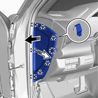

|
Remove in this Direction (1) |

|
Remove in this Direction (2) |
(b) Pull the instrument side panel LH in the direction indicated by the arrow (2) shown in the illustration to disengage the 3 guides and remove it.
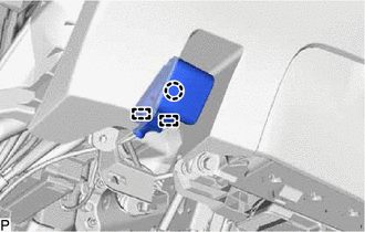
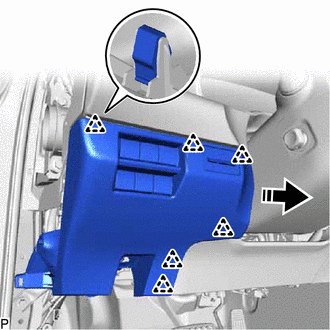
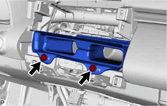
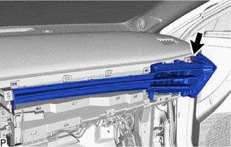
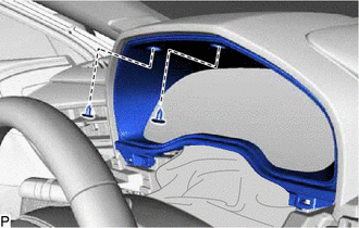
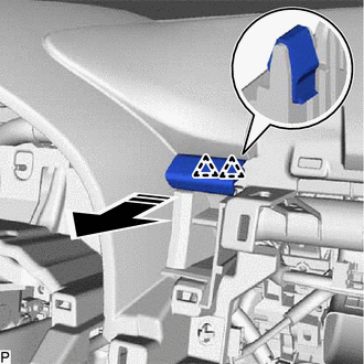
8. REMOVE NO. 1 INSTRUMENT PANEL UNDER COVER SUB-ASSEMBLY
|
(a) Remove the 2 screws <C>. |
|
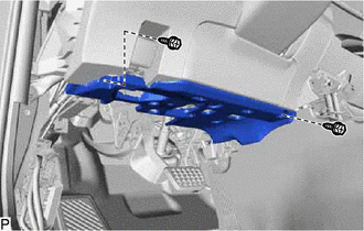
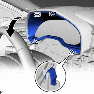
(b) Disengage the 2 claws and 2 guides as shown in the illustration.
|
|
Remove in this Direction |
|
(c) Disengage the 2 claws to disconnect the DLC3 connector. |
|
|
(d) Disconnect the connector and disengage the 2 clamps to remove the No. 1 instrument panel under cover sub-assembly. |
|
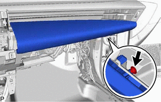
9. DISCONNECT HOOD LOCK CONTROL LEVER SUB-ASSEMBLY
|
(a) Disengage the claw and 2 guides to disconnect the hood lock control lever sub-assembly. |
|
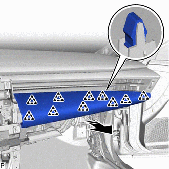
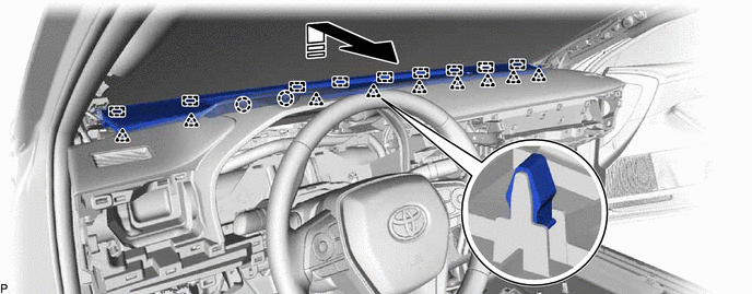
10. REMOVE NO. 1 INSTRUMENT PANEL SUB-ASSEMBLY
(a) Disengage the 6 clips as shown in the illustration.
|
|
Remove in this Direction |
|
(b) Disengage the clamp. |
|
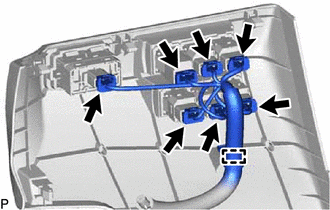
(c) Disconnect each connector to remove the No. 1 instrument panel sub-assembly.
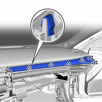
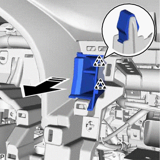
11. REMOVE LOWER NO. 2 INSTRUMENT PANEL FINISH PANEL
(a) Disengage the 6 clips as shown in the illustration to remove the lower No. 2 instrument panel finish panel.
|
|
Remove in this Direction |
12. REMOVE LOWER NO. 1 INSTRUMENT PANEL AIRBAG ASSEMBLY
Click here
13. REMOVE CENTER NO. 1 INSTRUMENT CLUSTER FINISH PANEL
(a) Disengage the 2 claws and clip as shown in the illustration to remove the center No. 1 instrument cluster finish panel.
|
|
Remove in this Direction |
14. REMOVE CENTER NO. 2 INSTRUMENT CLUSTER FINISH PANEL
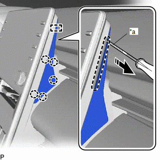
(a) Using a screwdriver, disengage the 5 claws and guide as shown in the illustration to remove the center No. 2 instrument cluster finish panel.
|
*a |
Protective Tape |

|
Place Hand Here |
|
|
Remove in this Direction |
HINT:
Tape the screwdriver tip before use.
15. REMOVE RADIO AND DISPLAY RECEIVER ASSEMBLY WITH BRACKET
Click here
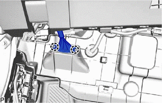
16. REMOVE NO. 2 HEATER TO REGISTER DUCT SUB-ASSEMBLY
|
(a) Remove the 2 screws <C> and No. 2 heater to register duct sub-assembly. |
|
17. REMOVE FRONT DOOR SCUFF PLATE RH
HINT:
Use the same procedure as for the LH side.
18. REMOVE COWL SIDE TRIM SUB-ASSEMBLY RH
HINT:
Use the same procedure as for the LH side.
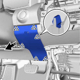
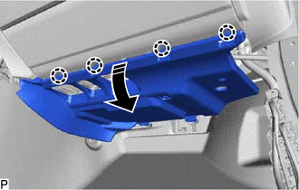
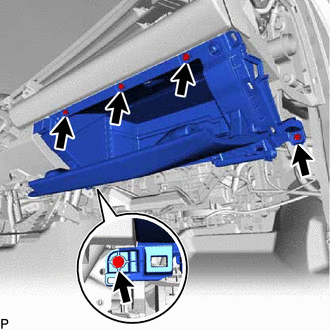
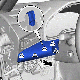
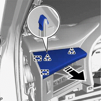
19. REMOVE NO. 2 INSTRUMENT PANEL UNDER COVER SUB-ASSEMBLY
(a) Disengage the 4 claws as shown in the illustration.
|
|
Remove in this Direction |
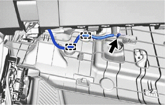
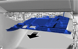
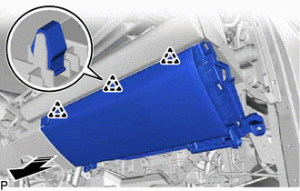
(b) Disengage the 2 guides as shown in the illustration.
|
|
Remove in this Direction |
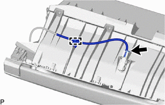
|
(c) Disengage the clamp. |
|
(d) Disconnect the connector to remove the No. 2 instrument panel under cover sub-assembly.
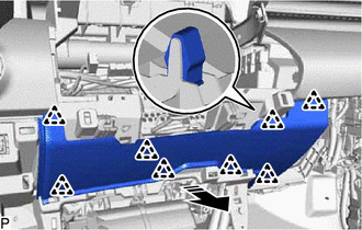
20. REMOVE GLOVE COMPARTMENT PLATE
(a) Disengage the 4 clips as shown in the illustration to remove the glove compartment plate.
|
|
Remove in this Direction |
21. DISCONNECT FRONT DOOR OPENING TRIM WEATHERSTRIP RH
|
(a) Disconnect the front door opening trim weatherstrip RH. |
|
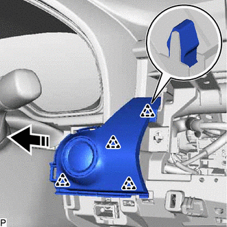
22. REMOVE INSTRUMENT SIDE PANEL RH
(a) Pull the instrument side panel RH in the direction indicated by the arrow (1) shown in the illustration to disengage the 2 claws and 3 clips.
|
|
Remove in this Direction (1) |
|
|
Remove in this Direction (2) |
(b) Pull the instrument side panel RH in the direction indicated by the arrow (2) shown in the illustration to disengage the 3 guides and remove it.
23. REMOVE LOWER NO. 2 INSTRUMENT PANEL AIRBAG ASSEMBLY
Click here
24. REMOVE LOWER INSTRUMENT PANEL SUB-ASSEMBLY
|
(a) Remove the 5 screws <C>. |
|
(b) Disengage the 3 clips as shown in the illustration.
|
|
Remove in this Direction |
|
(c) Disengage the clamp and disconnect the connector to remove the lower instrument panel sub-assembly. |
|
25. REMOVE LOWER CENTER INSTRUMENT PANEL FINISH PANEL
(a) Disengage the 8 clips as shown in the illustration to remove the lower center instrument panel finish panel.
|
|
Remove in this Direction |
26. REMOVE NO. 2 INSTRUMENT PANEL GARNISH SUB-ASSEMBLY
|
(a) Remove the screw <D>. |
|
(b) Disengage the 10 clips as shown in the illustration to remove the No. 2 instrument panel garnish sub-assembly.
|
|
Remove in this Direction |
27. REMOVE NO. 2 INSTRUMENT CLUSTER FINISH PANEL GARNISH
(a) Disengage the 5 clips and 2 guides as shown in the illustration to remove the No. 2 instrument cluster finish panel garnish.
|
|
Remove in this Direction |
28. REMOVE NO. 4 INSTRUMENT PANEL REGISTER ASSEMBLY
|
(a) Remove the screw <D>. |
|
(b) Disengage the 9 clips as shown in the illustration to remove the No. 4 instrument panel register assembly.
|
|
Remove in this Direction |
29. REMOVE INSTRUMENT CLUSTER FINISH PANEL GARNISH ASSEMBLY
(a) Disengage the claw and 2 clips as shown in the illustration to remove the instrument cluster finish panel garnish assembly.
|
|
Remove in this Direction |
30. REMOVE LOWER INSTRUMENT PANEL FINISH PANEL ASSEMBLY
(a) Disengage the 4 clips as shown in the illustration.
|
|
Remove in this Direction |
(b) Disconnect the connector to remove the lower instrument panel finish panel assembly.
31. REMOVE NO. 1 INSTRUMENT PANEL GARNISH SUB-ASSEMBLY
(a) Disengage the 5 clips as shown in the illustration to remove the No. 1 instrument panel garnish sub-assembly.
|
|
Remove in this Direction |
32. REMOVE INSTRUMENT CLUSTER FINISH PANEL SUB-ASSEMBLY
(a) Using a moulding remover, disengage the 4 clips and 2 guides as shown in the illustration.
|
|
Insert Moulding Remover Here |
|
|
Remove in this Direction |
|
(b) Remove the 2 clips. |
|
(c) Disengage the 2 clips and 2 guides as shown in the illustration to remove the instrument cluster finish panel sub-assembly.
|
|
Remove in this Direction |
33. REMOVE COMBINATION METER ASSEMBLY
Click here
34. REMOVE NO. 1 INSTRUMENT CLUSTER FINISH PANEL GARNISH
(a) Disengage the 2 clips and 2 guides as shown in the illustration to remove the No. 1 instrument cluster finish panel garnish.
|
|
Remove in this Direction |
35. REMOVE NO. 1 INSTRUMENT PANEL REGISTER ASSEMBLY
(a) Disengage the 4 clips as shown in the illustration to remove the No. 1 instrument panel register assembly.
|
|
Remove in this Direction |
36. REMOVE NO. 3 INSTRUMENT CLUSTER FINISH PANEL GARNISH
(a) Disengage the 2 clips as shown in the illustration to remove the No. 3 instrument cluster finish panel garnish.
|
|
Remove in this Direction |
37. REMOVE NO. 2 INSTRUMENT CLUSTER MOULDING
(a) Disengage the 2 clips as shown in the illustration to remove the No. 2 instrument cluster moulding.
|
|
Remove in this Direction |
38. REMOVE FRONT PILLAR GARNISH LH
Click here
39. REMOVE FRONT PILLAR GARNISH RH
HINT:
Use the same procedure as for the LH side.
40. REMOVE NO. 1 DEFROSTER NOZZLE GARNISH
(a) Disengage the 2 claws, 9 clips and 9 guides as shown in the illustration.
|
|
Remove in this Direction |
- |
- |
(b) Disconnect the connector to remove the No. 1 defroster nozzle garnish.
41. REMOVE FRONT NO. 2 SPEAKER ASSEMBLY (for LH Side)
Click here
42. REMOVE FRONT NO. 4 SPEAKER ASSEMBLY (for 14 Speakers)
Click here
43. REMOVE FRONT NO. 2 SPEAKER ASSEMBLY (for RH Side)
HINT:
Use the same procedure as for the LH side.
44. ALIGN FRONT WHEELS FACING STRAIGHT AHEAD
45. REMOVE HORN BUTTON ASSEMBLY
Click here
46. REMOVE STEERING WHEEL ASSEMBLY
Click here
47. REMOVE LOWER STEERING COLUMN COVER
for Manual Tilt and Manual Telescopic Steering Column: Click here
for Power Tilt and Power Telescopic Steering Column: Click here
48. REMOVE UPPER STEERING COLUMN COVER
for Manual Tilt and Manual Telescopic Steering Column: Click here
for Power Tilt and Power Telescopic Steering Column: Click here
49. REMOVE WINDSHIELD WIPER SWITCH ASSEMBLY
Click here
50. REMOVE TURN SIGNAL SWITCH
Click here
51. DISCONNECT NO. 2 INSTRUMENT PANEL WIRE
Click here
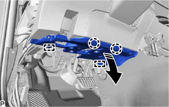
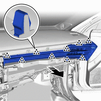
52. REMOVE INSTRUMENT PANEL SAFETY PAD SUB-ASSEMBLY
(a) Disengage the 2 claws to disconnect the cooler (room temp. sensor) thermistor.
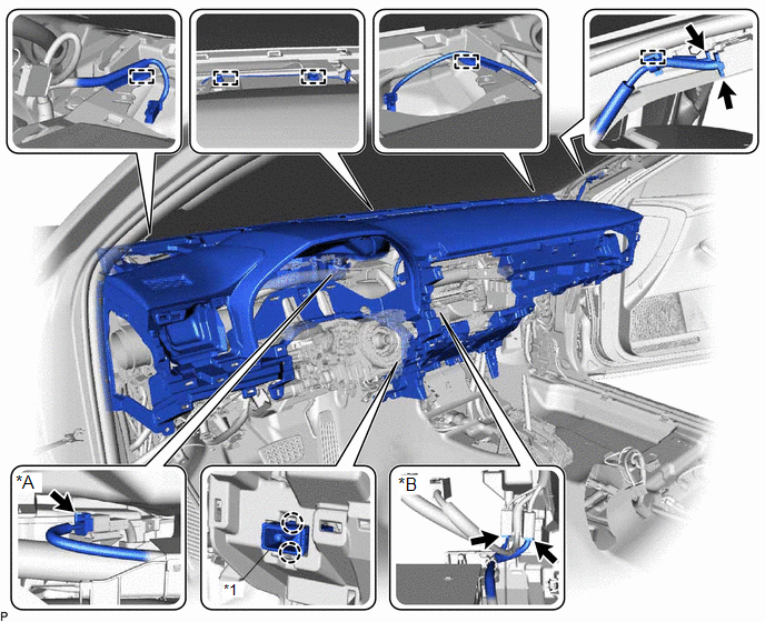
|
*A |
w/ Headup Display |
*B |
w/ Manual (SOS) Switch |
|
*1 |
Cooler (Room Temp. Sensor) Thermistor |
- |
- |
(b) Disconnect each connector.
(c) Disengage each clamp.
(d) Remove the 2 clips.

|
*a |
Bolt <A> |
*b |
Bolt <B> |
|
*c |
Clip |
*d |
Nut <E> |
(e) Remove the 4 bolts <B>, 2 bolts <A> and nut <E>.
(f) Disengage the 5 guides and remove the instrument panel safety pad sub-assembly as shown in the illustration.
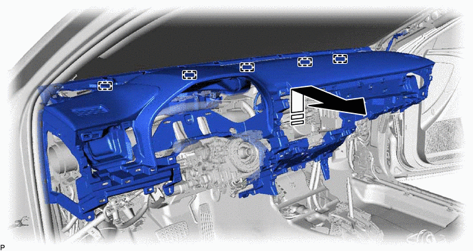
|
|
Remove in this Direction |
- |
- |
NOTICE:
- Do not damage the instrument panel safety pad sub-assembly.
- Do not allow the wire harnesses to interfere with the surrounding parts.
|
|
|