| Last Modified: 08-21-2023 | 6.11:8.1.0 | Doc ID: RM100000001ATVT |
| Model Year Start: 2019 | Model: Avalon | Prod Date Range: [04/2018 - ] |
| Title: NAVIGATION / MULTI INFO DISPLAY: NAVIGATION SYSTEM (for Gasoline Model): Voice Guidance Circuit between Radio Receiver and Stereo Component Amplifier; 2019 - 2022 MY Avalon [04/2018 - ] | ||
|
Voice Guidance Circuit between Radio Receiver and Stereo Component Amplifier |
DESCRIPTION
This circuit is used when the voice switch of the steering pad switch assembly is pushed.
Using this circuit, the radio and display receiver assembly sends signals to the stereo component amplifier assembly.
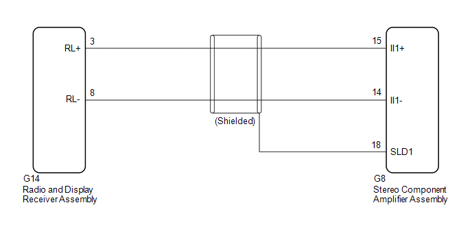
WIRING DIAGRAM
PROCEDURE
|
1. |
CHECK HARNESS AND CONNECTOR (RADIO AND DISPLAY RECEIVER ASSEMBLY - STEREO COMPONENT AMPLIFIER ASSEMBLY) |
(a) Disconnect the G14 radio and display receiver assembly connector.
(b) Disconnect the G8 stereo component amplifier assembly connector.
(c) Measure the resistance according to the value(s) in the table below.
Standard Resistance:
|
Tester connection |
Condition |
Specified condition |
|---|---|---|
|
G14-3 (RL+) - G8-15 (II1+) |
Always |
Below 1 Ω |
|
G14-8 (RL-) - G8-14 (II1-) |
Always |
Below 1 Ω |
|
G8-18 (SLD1) - Body ground |
Always |
10 kΩ or higher |
|
G14-3 (RL+) or G8-15 (II1+) - Body ground |
Always |
10 kΩ or higher |
|
G14-8 (RL-) or G8-14 (II1-) - Body ground |
Always |
10 kΩ or higher |
| OK |

|
PROCEED TO NEXT SUSPECTED AREA SHOWN IN PROBLEM SYMPTOMS TABLE
|
![2019 - 2020 MY Avalon [04/2018 - 08/2020]; NAVIGATION / MULTI INFO DISPLAY: NAVIGATION SYSTEM (for Gasoline Model): PROBLEM SYMPTOMS TABLE](/t3Portal/stylegraphics/info.gif)
| NG |
|
REPAIR OR REPLACE HARNESS OR CONNECTOR |
|
|
|