| Last Modified: 08-21-2023 | 6.11:8.1.0 | Doc ID: RM100000001ATPO |
| Model Year Start: 2019 | Model: Avalon HV | Prod Date Range: [04/2018 - 08/2020] |
| Title: VEHICLE PROXIMITY NOTIFICATION SYSTEM: VEHICLE PROXIMITY NOTIFICATION SYSTEM: Communication between Vehicle Proximity Notification System and Diagnostic Tool is not Possible; 2019 - 2020 MY Avalon Avalon HV [04/2018 - 08/2020] | ||
|
Communication between Vehicle Proximity Notification System and Diagnostic Tool is not Possible |
DESCRIPTION
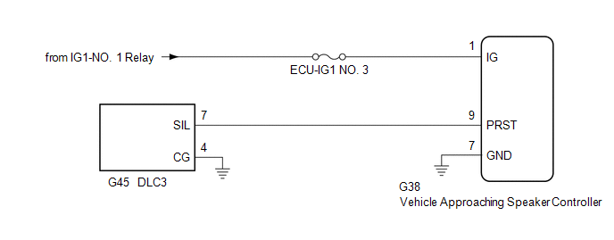
The vehicle approaching speaker controller communicates with the Techstream through the DLC3.
WIRING DIAGRAM

CAUTION / NOTICE / HINT
NOTICE:
Inspect the fuses for circuits related to this system before performing the following procedure.
HINT:
The vehicle approaching speaker controller and Techstream communicate using SIL communication.
PROCEDURE
|
1. |
CHECK FOR DTC |
(a) Connect the Techstream to the DLC3.
(b) Turn the power switch on (IG).
(c) Turn the Techstream on.
(d) Enter the following menus: Health Check.
|
Result |
Proceed to |
|---|---|
|
Communication with the vehicle approaching speaker controller is possible |
A |
|
Communication with the vehicle approaching speaker controller is not possible |
B |
| A |

|
|
|
2. |
CHECK HARNESS AND CONNECTOR (IG POWER SOURCE - VEHICLE APPROACHING SPEAKER CONTROLLER) |
(a) Disconnect the G38 vehicle approaching speaker controller connector.
(b) Measure the voltage according to the value(s) in the table below.
Standard Voltage:
|
Tester Connection |
Condition |
Specified Condition |
|---|---|---|
|
G38-1 (IG) - Body ground |
Power switch on (IG) |
11 to 14 V |
| NG |

|
REPAIR OR REPLACE HARNESS OR CONNECTOR |
|
|
3. |
CHECK HARNESS AND CONNECTOR (VEHICLE APPROACHING SPEAKER CONTROLLER - BODY GROUND) |
(a) Measure the resistance according to the value(s) in the table below.
Standard Resistance:
|
Tester Connection |
Condition |
Specified Condition |
|---|---|---|
|
G38-7 (GND) - Body ground |
Always |
Below 1 Ω |
| NG |

|
REPAIR OR REPLACE HARNESS OR CONNECTOR |
|
|
4. |
CHECK HARNESS AND CONNECTOR (DLC3 - VEHICLE APPROACHING SPEAKER CONTROLLER) |
(a) Measure the resistance according to the value(s) in the table below.
Standard Resistance:
|
Tester Connection |
Condition |
Specified Condition |
|---|---|---|
|
G45-7 (SIL) - G38-9 (PRST) |
Always |
Below 1 Ω |
|
G45-7 (SIL) or G38-9 (PRST) - Body ground |
Always |
10 kΩ or higher |
| NG |

|
REPAIR OR REPLACE HARNESS OR CONNECTOR |
|
|
5. |
CHECK HARNESS AND CONNECTOR (DLC3 - BODY GROUND) |
(a) Measure the resistance according to the value(s) in the table below.
Standard Resistance:
|
Tester Connection |
Condition |
Specified Condition |
|---|---|---|
|
G45-4 (CG) - Body ground |
Always |
Below 1 Ω |
| OK |

|
| NG |

|
REPAIR OR REPLACE HARNESS OR CONNECTOR |
|
|
|
