| Last Modified: 08-21-2023 | 6.11:8.1.0 | Doc ID: RM100000001AOCY |
| Model Year Start: 2019 | Model: Avalon HV | Prod Date Range: [04/2018 - ] |
| Title: A25A-FXS (ENGINE MECHANICAL): REAR CRANKSHAFT OIL SEAL: INSTALLATION; 2019 - 2022 MY Avalon HV [04/2018 - ] | ||
INSTALLATION
CAUTION / NOTICE / HINT
NOTICE:
This procedure includes the installation of small-head bolts. Refer to Small-Head Bolts of Basic Repair Hint to identify the small-head bolts.
Click here
![2019 - 2022 MY Avalon Avalon HV [04/2018 - ]; INTRODUCTION: REPAIR INSTRUCTION: PRECAUTION](/t3Portal/stylegraphics/info.gif)
PROCEDURE
1. INSTALL REAR ENGINE OIL SEAL
(a) Using height adjustment attachments and plate lift attachments, place the engine assembly on a flat level surface.
NOTICE:
- Using height adjustment attachments and plate lift attachments, keep the engine assembly level.
- To prevent the No. 2 oil pan sub-assembly from deforming, do not place any attachments under the No. 2 oil pan sub-assembly of the engine assembly.
- Using an engine sling device and engine lift, secure the engine assembly before servicing.
(b) Apply MP grease to the lip of a new rear engine oil seal.
NOTICE:
- Keep the lip free from foreign matter.
- Do not allow MP grease to contact the dust seal.
|
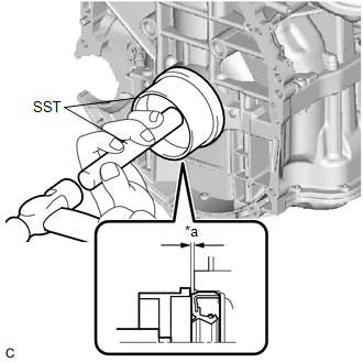
(c) Using SST and a hammer, tap in the rear engine oil seal. SST: 09223-15030 SST: 09950-70010 09951-07150 Standard Depth: -0.9 to 1.1 mm (-0.0354 to 0.0433 in.) (From the edge of the cylinder block sub-assembly and stiffening crankcase assembly) NOTICE: Do not tap in the rear engine oil seal at an angle. |
|
2. INSTALL NO. 1 CRANKSHAFT POSITION SENSOR PLATE
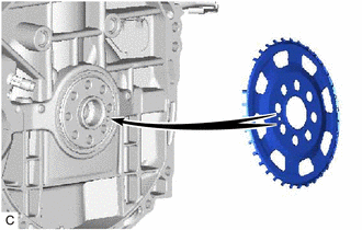
(a) Type A:
|
(1) Install the No. 1 crankshaft position sensor plate. HINT: Align the pin hole of the No. 1 crankshaft position sensor plate with the pin of the crankshaft. |
|
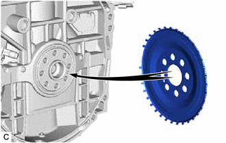
(b) Type B:
|
(1) Install the No. 1 crankshaft position sensor plate. HINT: Align the pin hole of the No. 1 crankshaft position sensor plate with the pin of the crankshaft. |
|
3. INSTALL FLYWHEEL SUB-ASSEMBLY
|
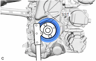
(a) Using SST, hold the crankshaft pulley assembly. SST: 09213-54015 SST: 09330-00021 |
|
(b) Clean the bolts and bolt holes.
(c) Apply adhesive to 2 or 3 threads at the end of each of 8 new bolts.
Adhesive:
Toyota Genuine Adhesive 1324, Three Bond 1324 or equivalent
|
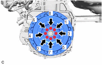
(d) Install the flywheel sub-assembly with the 8 bolts. Uniformly tighten the 8 bolts in the sequence shown in the illustration. Torque: 150 N·m {1530 kgf·cm, 111 ft·lbf} NOTICE: Do not start the engine for at least 1 hour after installing the flywheel sub-assembly. |
|
4. INSTALL TRANSMISSION INPUT DAMPER ASSEMBLY
|
(a) Using SST, hold the crankshaft pulley assembly. SST: 09213-54015 SST: 09330-00021 |
|

|
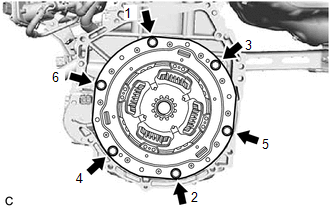
(b) Install the transmission input damper assembly to the flywheel sub-assembly with the 6 bolts. Uniformly tighten the 6 bolts in the order shown in the illustration. Torque: 30 N·m {306 kgf·cm, 22 ft·lbf} NOTICE:
|
|
5. INSTALL HYBRID VEHICLE TRANSAXLE ASSEMBLY
Click here
|
|
|