| Last Modified: 08-21-2023 | 6.11:8.1.0 | Doc ID: RM100000001AO1J |
| Model Year Start: 2019 | Model: Avalon HV | Prod Date Range: [04/2018 - ] |
| Title: LIGHTING (EXT): LIGHTING SYSTEM (for HV Model without Cornering Light): Automatic High Beam Switch Indicator does not Come ON; 2019 - 2022 MY Avalon HV [04/2018 - ] | ||
|
Automatic High Beam Switch Indicator does not Come ON |
DESCRIPTION
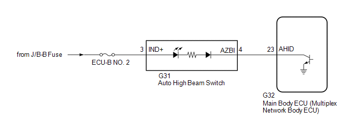
When the automatic high beam system is on, the main body ECU (multiplex network body ECU) illuminates the auto high beam switch indicator.
WIRING DIAGRAM

CAUTION / NOTICE / HINT
NOTICE:
PROCEDURE
|
1. |
PERFORM ACTIVE TEST USING TECHSTREAM |
(a) Connect the Techstream to the DLC3.
(b) Turn the power switch on (IG).
(c) Turn the Techstream on.
(d) Enter the following menus: Body Electrical / Main Body / Active Test.
(e) Perform the Active Test according to the display on the Techstream.
Body Electrical > Main Body > Active Test
|
Tester Display |
Measurement Item |
Control Range |
Diagnostic Note |
|---|---|---|---|
|
Automatic High Beam Switch Light |
Auto high beam switch indicator light |
OFF or ON |
- |
Body Electrical > Main Body > Active Test
|
Tester Display |
|---|
|
Automatic High Beam Switch Light |
OK:
Auto high beam switch indicator light illuminates.
| OK |

|
|
|
2. |
INSPECT AUTO HIGH BEAM SWITCH |
(a) Remove the auto high beam switch.
(b) Inspect the auto high beam switch.
| NG |

|
|
|
3. |
CHECK HARNESS AND CONNECTOR (POWER SOURCE - AUTO HIGH BEAM SWITCH) |
(a) Measure the voltage according to the value(s) in the table below.
Standard Voltage:
|
Tester Connection |
Condition |
Specified Condition |
|---|---|---|
|
G31-3 (IND+) - Body ground |
Power switch off |
11 to 14 V |
| NG |

|
REPAIR OR REPLACE HARNESS OR CONNECTOR |
|
|
4. |
CHECK HARNESS AND CONNECTOR (AUTO HIGH BEAM SWITCH - MAIN BODY ECU (MULTIPLEX NETWORK BODY ECU)) |
(a) Disconnect the G32 main body ECU (multiplex network body ECU) connector.
(b) Measure the resistance according to the value(s) in the table below.
Standard Resistance:
|
Tester Connection |
Condition |
Specified Condition |
|---|---|---|
|
G31-4 (AZBI) - G32-23 (AHID) |
Always |
Below 1 Ω |
|
G31-4 (AZBI) or G32-23 (AHID) - Body ground |
Always |
10 kΩ or higher |
| OK |

|
| NG |

|
REPAIR OR REPLACE HARNESS OR CONNECTOR |
|
|
|
![2019 - 2020 MY Avalon HV [04/2018 - 08/2020]; THEFT DETERRENT / KEYLESS ENTRY: SMART KEY SYSTEM (for Start Function, HV Model): REGISTRATION](/t3Portal/stylegraphics/info.gif)
