| Last Modified: 09-10-2025 | 6.11:8.1.0 | Doc ID: RM100000001ANLB |
| Model Year Start: 2019 | Model: Avalon HV | Prod Date Range: [04/2018 - ] |
| Title: BRAKE CONTROL / DYNAMIC CONTROL SYSTEMS: ELECTRONICALLY CONTROLLED BRAKE SYSTEM (for HV Model): C14B6; Stroke Sensor / Reaction Force Pressure Sensor Output Inconsistent; 2019 - 2022 MY Avalon HV [04/2018 - ] | ||
|
DTC |
C14B6 |
Stroke Sensor / Reaction Force Pressure Sensor Output Inconsistent |
DESCRIPTION
|
DTC No. |
Detection Item |
INF Code |
DTC Detection Condition |
Trouble Area |
MIL |
Note |
|---|---|---|---|---|---|---|
|
C14B6 |
Stroke Sensor / Reaction Force Pressure Sensor Output Inconsistent |
209 |
The difference between brake pedal stroke sensor assembly output value and reaction force pressure sensor output value is above the threshold for a certain period of time. |
|
Comes on |
|
MONITOR DESCRIPTION
The skid control ECU (brake booster with master cylinder assembly) monitors the ratio of output value of the brake pedal stroke sensor assembly and reaction force pressure sensor.
When in linear mode (switching solenoid (SSA) on), the brake pedal is being operated and the ratio of the output value of the brake pedal stroke sensor assembly and reaction force pressure sensor is outside the normal range, the skid control ECU (brake booster with master cylinder assembly) judges that the ratio of the output value of the brake pedal stroke sensor assembly and reaction force pressure sensor is abnormal and illuminates the MIL and stores this DTC.
MONITOR STRATEGY
|
Related DTCs |
C14B6: Brake stroke/reaction force pressure correlation |
|
Required Sensors/Components(Main) |
Brake actuator (brake booster with master cylinder assembly) Brake pedal stroke sensor assembly |
|
Required Sensors/Components(Related) |
Skid control ECU (brake booster with master cylinder assembly) Brake actuator (brake booster with master cylinder assembly) Brake pedal stroke sensor assembly Stop light switch assembly |
|
Frequency of Operation |
Continuous |
|
Duration |
0.5 seconds |
|
MIL Operation |
Immediately |
|
Sequence of Operation |
None |
TYPICAL ENABLING CONDITIONS
|
Monitor runs whenever the following DTCs are not stored |
C0562 (Brake pedal stroke sensor assembly voltage circuit/open) C0594 (Pump motor performance) C0597 (EEPROM malfunction) C0597 (Lost communication) C0597 (CPU malfunction) C0597 (IC malfunction) C121D (Pump motor open circuit) C121E (Pump motor circuit high) C1241 (Brake system voltage circuit low) C1241 (Speed sensor voltage circuit low) C124B (Brake pedal stroke sensor assembly invalid data) C1256 (Accumulator pressure too low) C12FA (Main relay circuit low) C12FB (Main relay circuit high) C1345 (Linear solenoid open current learning not complete) C1392 (Brake pedal stroke sensor learning not complete) C139D (Linear solenoid (SLA) stuck on) C13C1, C13CA, C14F2, C14FB (Linear solenoid range/performance) C13C2, C13CB, C14F3, C14FC (Linear solenoid circuit low) C13C3, C13CC, C14F4, C14FD (Linear solenoid circuit high) C13CD (Brake pressure too low) C13CE (Brake pressure too high) C1451 (High pressure hydraulic tube air bleeding not complete) C14B0 (Reaction force pressure sensor voltage circuit check) C14B1 (Reaction force pressure sensor lost communication) C14B2 (Reaction force pressure sensor internal malfunction) C14B3 (Reaction force pressure sensor exceeded learning limit) C14B4 (Reaction force pressure sensor intermittent/erratic) C14B5 (Reaction force pressure sensor invalid data) C14C0 (Servo pressure sensor voltage circuit check) C14C1 (Servo pressure sensor lost communication) C14C2 (Servo pressure sensor internal malfunction) C14C3 (Servo pressure sensor exceeded learning limit) C14C4 (Servo pressure sensor intermittent/erratic) C14C5 (Servo pressure sensor invalid data) C14D0 (Accumulator pressure sensor voltage circuit check) C14D1 (Accumulator pressure sensor lost communication) C14D2 (Accumulator pressure sensor internal malfunction) C14D3 (Accumulator pressure sensor intermittent/erratic) C14D4 (Case 1) (Accumulator pressure sensor invalid data) C14D4 (Case 2) (Accumulator pressure sensor intermittent) C14D5 (Accumulator pressure sensor stuck) C14DE (Main relay voltage circuit low) C14F7 (Switching solenoid (SGH) stuck on) P057C, P05DD (Brake pedal stroke sensor assembly open circuit) P057D, P05DE (Brake pedal stroke sensor assembly circuit high) P057E, P05DF (Brake pedal stroke sensor assembly intermittent/erratic) P05E0 (Brake pedal stroke sensor assembly "1"/"2" correlation) |
|
All of the following conditions are met |
- |
|
Brake pedal stroke sensor assembly fail |
Not detected |
|
Reaction force pressure sensor fail |
Not detected |
|
Brake-by-wire controlled mode |
On |
|
Brake pedal operation |
On |
TYPICAL MALFUNCTION THRESHOLDS
|
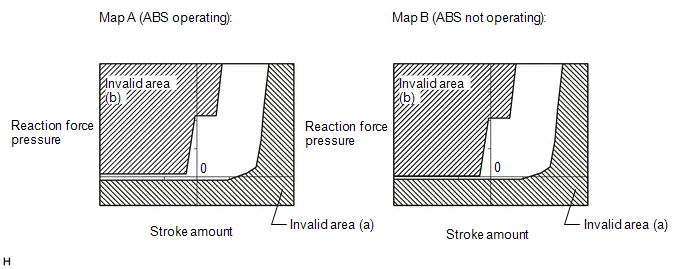
Ratio of the output value of the brake pedal stroke sensor assembly and reaction force pressure sensor |
Within the invalid area (a) or invalid area (b) of the following Map A or Map B |
COMPONENT OPERATING RANGE
|
All of the following conditions are met |
- |
|
Brake pedal stroke sensor assembly fail |
Not detected |
|
Reaction force pressure sensor fail |
Not detected |
|
Brake-by-wire controlled mode |
On |
|
Brake pedal operation |
On |
|
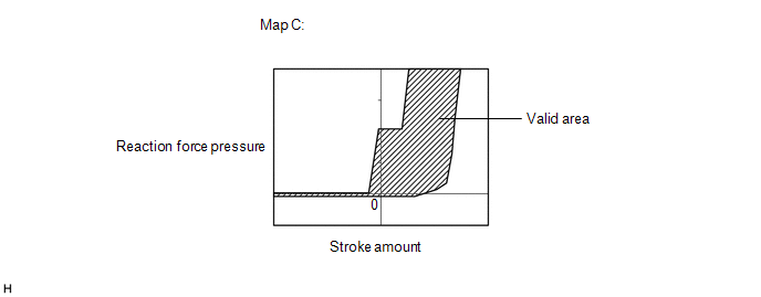
Ratio of the output value of the brake pedal stroke sensor assembly and reaction force pressure sensor |
Within the valid area of the Map C |
CONFIRMATION DRIVING PATTERN
- Connect the Techstream to the DLC3.
- Turn the power switch on (IG).
- Turn the Techstream on.
- Clear the DTCs (even if no DTCs are stored, perform the clear DTC procedure).
- Turn the power switch off.
- Turn the power switch on (IG).
- Turn the Techstream on.
- Depress the brake pedal 1 or more times.
- Enter the following menus: Chassis / ABS/VSC/TRAC / Trouble Codes.
-
Read the DTCs.
HINT:
- If a DTC is output, the system is malfunctioning.
- If a DTC is not output, perform the following procedure.
-
If the DTCs are not output, perform a universal trip and check for permanent DTCs.
Click here
![2019 - 2022 MY Avalon HV [04/2018 - ]; BRAKE CONTROL / DYNAMIC CONTROL SYSTEMS: ELECTRONICALLY CONTROLLED BRAKE SYSTEM (for HV Model): DTC CHECK / CLEAR](/t3Portal/stylegraphics/info.gif)
HINT:
- If a permanent DTC is output, the system is malfunctioning.
- If no permanent DTCs are output, the system is normal.
CAUTION / NOTICE / HINT
NOTICE:
After replacing the brake actuator (brake booster with master cylinder assembly) or brake pedal stroke sensor assembly perform linear solenoid valve offset learning, ABS holding solenoid valve learning, yaw rate and acceleration sensor zero point calibration and system information memorization after performing "Reset Memory".
Click here
PROCEDURE
PROCEDURE
|
1. |
CUSTOMER PROBLEM ANALYSIS (CHECK CONDITION WHEN MALFUNCTION OCCURRED) AND FREEZE FRAME DATA |
(a) Interview the customer to check the vehicle conditions when the brake warning light / yellow (minor malfunction) illuminated.
(b) Using the Techstream, read the "Shift Lever Position", "Vehicle Speed", "Yaw Rate Sensor", "Steering Angle Sensor", "Stop Light SW", "Stroke Sensor", "Reaction Force Pressure", "Servo Pressure" and "Accumulator Pressure" of the Freeze Frame Data stored when the DTC was stored.
HINT:
- Freeze Frame Data is only stored once when a DTC is stored.
- If other DTCs are output, repair any malfunctions related to those DTCs first, and then reproduce the conditions that caused DTC C14B6 to be stored based on the interview with the customer.
|

|
2. |
INSPECT BRAKE PEDAL STROKE SENSOR ASSEMBLY OUTPUT VOLTAGES AND WHEEL CYLINDER PRESSURE |
(a) Turn the power switch off.
(b) Mount a pedal effort gauge.
(c) Disconnect the A40 brake booster pump assembly connector.
(d) Depress the brake pedal 10 times or more until it becomes hard.
HINT:
Depressing the brake pedal with the connector of the brake booster pump assembly disconnected drops the accumulator pressure to approximately 0 MPa.
(e) Connect an LSPV gauge set.
(f) Select the Data List on the Techstream.
Click here
Chassis > ABS/VSC/TRAC > Data List
|
Tester Display |
Measurement Item |
Range |
Normal Condition |
Diagnostic Note |
|---|---|---|---|---|
|
Stroke Sensor |
Brake pedal stroke sensor |
Min.: 0.00 V, Max.: 5.00 V |
Brake pedal released: 0.65 to 1.35 V |
Reading increases when brake pedal is depressed |
Chassis > ABS/VSC/TRAC > Data List
|
Tester Display |
|---|
|
Stroke Sensor |
(g) Slowly depress the brake pedal and check the brake pedal stroke sensor assembly output voltages and the wheel cylinder pressure with respect to brake pedal depression force.
NOTICE:
Check the wheel cylinder pressure with the switching solenoid (SSA, SGH) off and an accumulator pressure of 0 MPa.
Standard Pressure:
for Front Right Wheel
|
Brake Effort [N (kgf, lbf)] |
Stroke Sensor [V] |
Hydraulic Pressure [MPa (kgf/cm2, psi)] |
|---|---|---|
|
200 (20, 45.0) |
1.52 to 2.22 |
0.04 (0.4, 5.8) to 2.04 (20.8, 296) |
|
500 (51, 112.4) |
1.81 to 2.51 |
2.06 (21.0, 299) to 4.06 (41.4, 589) |
for Front Left Wheel
|
Brake Effort [N (kgf, lbf)] |
Stroke Sensor [V] |
Hydraulic Pressure [MPa (kgf/cm2, psi)] |
|---|---|---|
|
200 (20, 45.0) |
1.52 to 2.22 |
0.04 (0.4, 5.8) to 2.04 (20.8, 296) |
|
500 (51, 112.4) |
1.81 to 2.51 |
2.06 (21.0, 299) to 4.06 (41.4, 589) |
| OK |

|
REPLACE BRAKE BOOSTER WITH MASTER CYLINDER ASSEMBLY Click here
|
| NG |
|
|
3. |
REPLACE BRAKE PEDAL STROKE SENSOR ASSEMBLY |
(a) Turn the power switch off.
(b) Reconnect the A40 brake booster pump assembly connector.
(c) Replace brake pedal stroke sensor assembly.
Click here
(d) Perform zero point calibration of the brake pedal stroke sensor assembly.
Click here
Chassis > ABS/VSC/TRAC > Utility
|
Tester Display |
|---|
|
ECB Utility |
|
|
4. |
RECONFIRM DTC |
(a) Clear the DTCs.
Click here
Chassis > ABS/VSC/TRAC > Clear DTCs
(b) Perform a road test under the same malfunction conditions recreated based on the Freeze Frame Data or customer problem analysis.
(c) Turn the power switch off and wait for 2 minutes or more.
(d) Turn the power switch on (IG).
(e) Check if the same DTC is output.
Click here
Chassis > ABS/VSC/TRAC > Trouble Codes
|
Result |
Proceed to |
|---|---|
|
DTC C14B6 is not output. |
A |
|
DTC C14B6 is output. |
B |
| A |
|
END |
| B |
|
REPLACE BRAKE BOOSTER WITH MASTER CYLINDER ASSEMBLY Click here
|
|
|
|