| Last Modified: 08-21-2023 | 6.11:8.1.0 | Doc ID: RM100000001AHZH |
| Model Year Start: 2019 | Model: Avalon HV | Prod Date Range: [04/2018 - 08/2020] |
| Title: METER / GAUGE / DISPLAY: METER / GAUGE SYSTEM (for HV Model): Vehicle Proximity Notification System Warning Message Display Malfunction; 2019 - 2020 MY Avalon HV [04/2018 - 08/2020] | ||
|
Vehicle Proximity Notification System Warning Message Display Malfunction |
DESCRIPTION
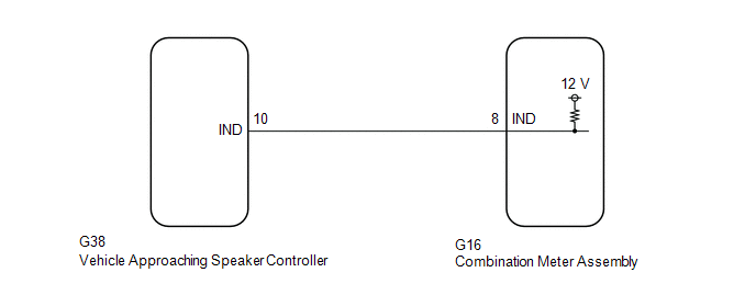
The combination meter assembly and vehicle approaching speaker controller are connected via direct line. If a malfunction occurs in the vehicle proximity notification system, the combination meter assembly receives a malfunction signal from the vehicle approaching speaker controller and outputs a warning.
WIRING DIAGRAM

CAUTION / NOTICE / HINT
NOTICE:
- When replacing the combination meter assembly, always replace it with a new one. If a combination meter assembly which was installed to another vehicle is used, the information stored in it will not match the information from the vehicle and a DTC may be stored.
- The following troubleshooting procedure is based on the assumption that the vehicle proximity notification system is normal. Confirm that the vehicle proximity notification system is not malfunctioning before performing the following procedure.
PROCEDURE
|
1. |
INSPECT COMBINATION METER ASSEMBLY (OUTPUT VOLTAGE) |

|
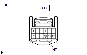
*a |
Front view of wire harness connector (to Vehicle Approaching Speaker Controller) |
(a) Disconnect the G38 vehicle approaching speaker controller connector.
(b) Measure the voltage according to the value(s) in the table below.
Standard Voltage:
|
Tester Connection |
Condition |
Specified Condition |
|---|---|---|
|
G38-10 (IND) - Body ground |
Power switch on (IG) |
11 to 14 V |
| NG |

|
|
|
2. |
INSPECT COMBINATION METER ASSEMBLY (WARNING MESSAGE) |

|
*a |
Front view of wire harness connector (to Vehicle Approaching Speaker Controller) |
(a) Turn the power switch off.
(b) Connect SST to terminal G38-10 (IND) and body ground.
SST: 09843-18040
(c) Turn the power switch on (IG).
(d) Check the combination meter assembly display.
|
Result |
Proceed to |
|---|---|
|
"Proximity Notification System Malfunction Visit Your Dealer" displayed on multi-information display |
A |
|
"Proximity Notification System Malfunction Visit Your Dealer" not displayed on multi-information display |
B |
| A |

|
| B |

|
|
3. |
CHECK HARNESS AND CONNECTOR (VEHICLE APPROACHING SPEAKER CONTROLLER - COMBINATION METER ASSEMBLY) |
(a) Disconnect the G16 combination meter assembly connector.
(b) Measure the resistance according to the value(s) in the table below.
Standard Resistance:
|
Tester Connection |
Condition |
Specified Condition |
|---|---|---|
|
G38-10 (IND) - G16-8 (IND) |
Always |
Below 1 Ω |
|
G38-10 (IND) or G16-8 (IND) - Body ground |
Always |
10 kΩ or higher |
| OK |

|
| NG |

|
REPAIR OR REPLACE HARNESS OR CONNECTOR |
|
|
|
![2019 - 2020 MY Avalon Avalon HV [04/2018 - 08/2020]; VEHICLE PROXIMITY NOTIFICATION SYSTEM: VEHICLE PROXIMITY NOTIFICATION SYSTEM: HOW TO PROCEED WITH TROUBLESHOOTING](/t3Portal/stylegraphics/info.gif)
