- Intelligent Clearance Sonar System
- Intuitive Parking Assist System
| Last Modified: 09-10-2025 | 6.11:8.1.0 | Doc ID: RM100000001AFXE |
| Model Year Start: 2019 | Model: Avalon HV | Prod Date Range: [04/2018 - 08/2020] |
| Title: REAR SUSPENSION: REAR TRAILING ARM: INSTALLATION; 2019 - 2020 MY Avalon HV Avalon [04/2018 - 08/2020] | ||
INSTALLATION
CAUTION / NOTICE / HINT
HINT:
- Use the same procedure for the RH side and LH side.
- The following procedure is for the LH side.
PROCEDURE
PROCEDURE
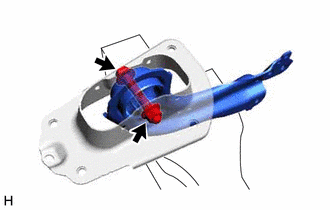
1. INSTALL REAR SUSPENSION ARM BRACKET
|
(a) Temporarily install the rear suspension arm bracket to the rear trailing arm assembly with the bolt and nut. NOTICE: Insert the bolt from the inside of the vehicle. |
|
|
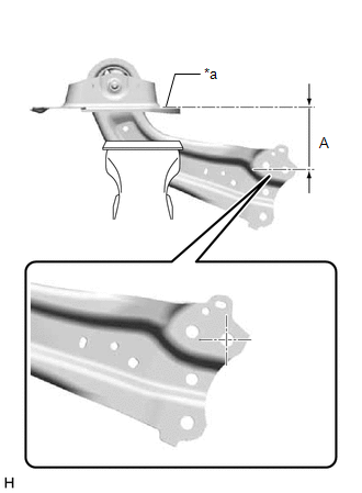
(b) Position the rear trailing arm assembly as shown in the illustration. Reference Length (A): 120 mm (4.72 in.) |
|
(c) Fully tighten the nut.
Torque:
120 N·m {1224 kgf·cm, 89 ft·lbf}
2. INSTALL REAR SUSPENSION ARM COVER
(a) Engage the 4 claws and install the rear suspension arm cover.
3. INSTALL REAR TRAILING ARM ASSEMBLY
(a) Using a transmission jack and a wooden block, support the rear No. 2 suspension arm assembly.
NOTICE:
- When jacking up the rear No. 2 suspension arm assembly, be sure to jack it up slowly.
- Make sure to perform this operation with the vehicle kept as low as possible.
(b) Install the rear trailing arm assembly to the vehicle with the 4 bolts.
Torque:
90 N·m {918 kgf·cm, 66 ft·lbf}
(c) Install the rear trailing arm assembly to the rear axle carrier sub-assembly with the 2 bolts.
Torque:
135 N·m {1377 kgf·cm, 100 ft·lbf}
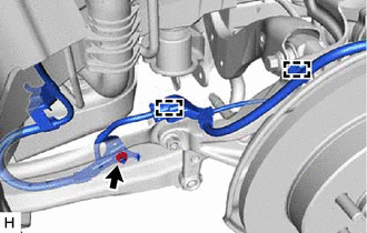
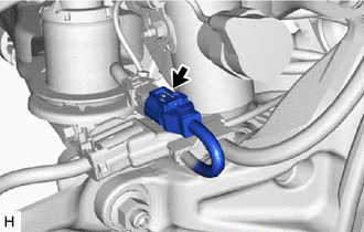
4. INSTALL NO. 2 PARKING BRAKE WIRE ASSEMBLY (w/o AVS)
|
(a) Install the No. 2 parking brake wire assembly to the rear trailing arm assembly with the nut. Torque: 15.5 N·m {158 kgf·cm, 11 ft·lbf} |
|
(b) Engage the 2 clamps.
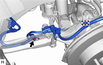
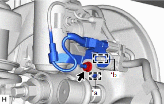
5. INSTALL NO. 2 PARKING BRAKE WIRE ASSEMBLY (w/ AVS)
|
(a) Install the No. 2 parking brake wire assembly to the rear trailing arm assembly with the nut. Torque: 15.5 N·m {158 kgf·cm, 11 ft·lbf} |
|
(b) Engage the clamp.
|
(c) Engage the guide and install the wire harness bracket. |
|
(d) Install the nut.
Torque:
8.5 N·m {87 kgf·cm, 75 in·lbf}
(e) Engage the clamp and install the No. 2 parking brake wire assembly to the wire harness bracket.
|
(f) Connect the connector. |
|
6. INSTALL REAR STABILIZER LINK ASSEMBLY
Click here
![2019 - 2022 MY Avalon HV Avalon [04/2018 - ]; REAR SUSPENSION: REAR STABILIZER BAR (for 2WD): INSTALLATION+](/t3Portal/stylegraphics/info.gif)
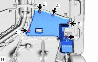
7. INSTALL NO. 1 FLOOR UNDER COVER (for HV Model)
|
(a) for RH Side: (1) Install the No. 1 floor under cover with the 2 grommets (B). (2) Install the bolt and clip (A). Torque: Bolt : 7.5 N·m {76 kgf·cm, 66 in·lbf} |
|
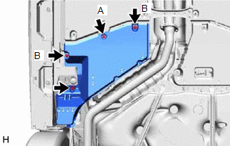
8. INSTALL NO. 2 FLOOR UNDER COVER (for HV Model)
|
(a) for LH Side: (1) Install the No. 2 floor under cover with the 2 grommets (B) and clip (C). (2) Install the bolt and clip (A). Torque: Bolt : 7.5 N·m {76 kgf·cm, 66 in·lbf} |
|
9. INSTALL NO. 1 FLOOR UNDER COVER (for Gasoline Model)
(a) for RH Side:
Click here
10. INSTALL NO. 2 FLOOR UNDER COVER (for Gasoline Model)
(a) for LH Side:
Click here
11. INSTALL REAR WHEEL
Click here
12. INSPECT AND ADJUST REAR WHEEL ALIGNMENT
Click here
13. PERFORM INITIALIZATION
for Gasoline Model:
|
|
|
|
Parking Assist Monitor System |
|
|
Panoramic View Monitor System |
|
for HV Model:
|
|
|
Parking Assist Monitor System |
|
|
Panoramic View Monitor System |
|
|
|
|