| Last Modified: 09-10-2025 | 6.11:8.1.0 | Doc ID: RM100000001A0G5 |
| Model Year Start: 2019 | Model: Avalon HV | Prod Date Range: [04/2018 - 08/2020] |
| Title: HYBRID / BATTERY CONTROL: HYBRID CONTROL SYSTEM (for NICKEL METAL HYDRIDE BATTERY): ECU Power Source Circuit; 2019 - 2020 MY Avalon HV [04/2018 - 08/2020] | ||
|
ECU Power Source Circuit |
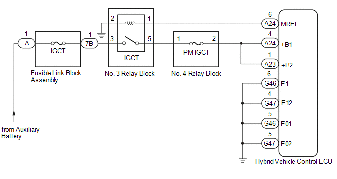
DESCRIPTION
If the power switch is on (IG), the hybrid vehicle control ECU applies current to the MREL terminal to turn the IGCT relay on. This supplies power to the +B1 and +B2 terminals.
WIRING DIAGRAM
CAUTION / NOTICE / HINT
NOTICE:
After turning the power switch off, waiting time may be required before disconnecting the cable from the negative (-) auxiliary battery terminal. Therefore, make sure to read the disconnecting the cable from the negative (-) auxiliary battery terminal notices before proceeding with work.
Click here
![2019 - 2022 MY Avalon Avalon HV [04/2018 - ]; INTRODUCTION: REPAIR INSTRUCTION: PRECAUTION](/t3Portal/stylegraphics/info.gif)
PROCEDURE
PROCEDURE
|
1. |
CHECK HYBRID VEHICLE CONTROL ECU (+B1, +B2 VOLTAGE) |
(a) Turn the power switch on (IG).
|
(b) Measure the voltage according to the value(s) in the table below. Standard Voltage:
|
|
(c) Turn the power switch off.
| NG |

|
|

|
2. |
CHECK HARNESS AND CONNECTOR (HYBRID VEHICLE CONTROL ECU - BODY GROUND) |
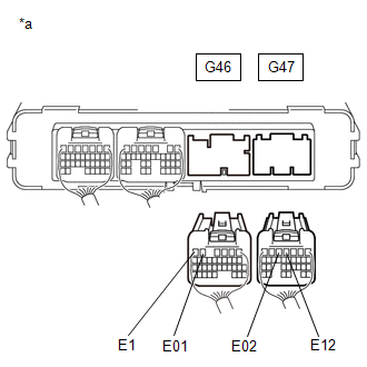
(a) Disconnect the G46 and G47 hybrid vehicle control ECU connectors.
|
(b) Measure the resistance according to the value(s) in the table below. Standard Resistance:
|
|
(c) Reconnect the G46 and G47 hybrid vehicle control ECU connectors.
| OK |
|
| NG |
|
REPAIR OR REPLACE HARNESS OR CONNECTOR |
|
3. |
CHECK HYBRID VEHICLE CONTROL ECU (MREL VOLTAGE) |
(a) Turn the power switch on (IG).
|
(b) Measure the voltage according to the value(s) in the table below. Standard Voltage:
|
|
(c) Turn the power switch off.
| NG |
|
|
|
4. |
CHECK FUSE (PM-IGCT) |
|
(a) Remove the PM-IGCT fuse from the No. 4 relay block. |
|
(b) Measure the resistance according to the value(s) in the table below.
Standard Resistance:
|
Tester Connection |
Condition |
Specified Condition |
|---|---|---|
|
PM-IGCT fuse |
Always |
Below 1 Ω |
(c) Install the PM-IGCT fuse.
| NG |
|
|
|
5. |
CHECK FUSIBLE LINK BLOCK ASSEMBLY (IGCT FUSE) |
(a) Disconnect the cable from the negative (-) auxiliary battery terminal.
(b) Disconnect the cable from the positive (+) auxiliary battery terminal.
|
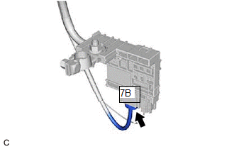
(c) Disconnect the 7B fusible link block assembly connector. |
|
|
(d) Measure the resistance according to the value(s) in the table below. Standard Resistance:
|
|
(e) Reconnect the 7B fusible link block assembly connector.
(f) Reconnect the cable to the positive (+) auxiliary battery terminal.
(g) Reconnect the cable to the negative (-) auxiliary battery terminal.
| NG |
|
|
|
6. |
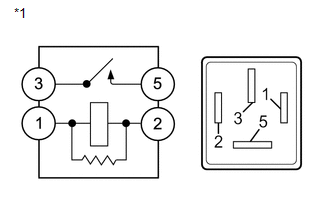
INSPECT RELAY (IGCT) |
|
(a) Remove the IGCT relay from the No. 3 relay block. |
|
|
(b) Measure the resistance according to the value(s) in the table below. Standard Resistance:
|
|
(c) Install the IGCT relay.
| NG |
|
REPLACE RELAY (IGCT) |
|
|
7. |
CHECK HARNESS AND CONNECTOR (NO. 4 RELAY BLOCK - HYBRID VEHICLE CONTROL ECU) |
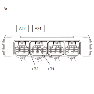
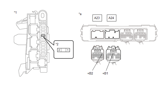
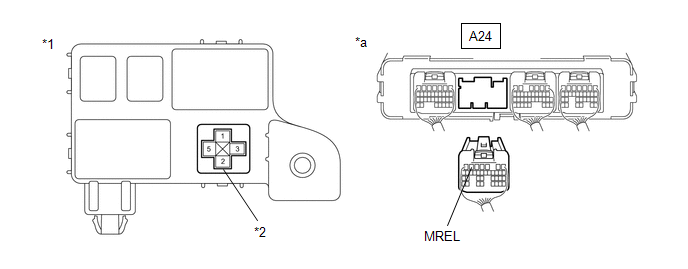
(a) Disconnect the A23 and A24 hybrid vehicle control ECU connectors.
(b) Remove the PM-IGCT fuse from the No. 4 relay block.
(c) Measure the resistance according to the value(s) in the table below.
|
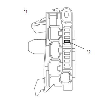
*1 |
No. 4 Relay Block |
*2 |
PM-IGCT Fuse Holder |
|
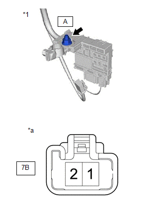
*a |
Rear view of wire harness connector (to Hybrid Vehicle Control ECU) |
- |
- |
Standard Resistance:
|
Tester Connection |
Condition |
Specified Condition |
|---|---|---|
|
A24-4 (+B1) - 2 (PM-IGCT fuse holder) |
Always |
Below 1 Ω |
|
A23-1 (+B2) - 2 (PM-IGCT fuse holder) |
Always |
Below 1 Ω |
(d) Reconnect the A23 and A24 hybrid vehicle control ECU connectors.
(e) Install the PM-IGCT fuse.
| NG |
|
REPAIR OR REPLACE HARNESS OR CONNECTOR |
|
|
8. |
CHECK HARNESS AND CONNECTOR (NO. 3 RELAY BLOCK - NO. 4 RELAY BLOCK) |
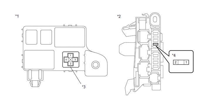
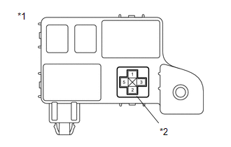
(a) Remove the IGCT relay from the No. 3 relay block.
(b) Remove the PM-IGCT fuse from the No. 4 relay block.
(c) Measure the resistance according to the value(s) in the table below.
|
*1 |
No. 3 Relay Block |
*2 |
No. 4 Relay Block |
|
*3 |
IGCT Relay Holder |
*4 |
PM-IGCT Fuse Holder |
Standard Resistance:
|
Tester Connection |
Condition |
Specified Condition |
|---|---|---|
|
5 (IGCT relay holder) - 1 (PM-IGCT fuse holder) |
Always |
Below 1 Ω |
(d) Install the PM-IGCT fuse.
(e) Install the IGCT relay.
| NG |
|
REPAIR OR REPLACE HARNESS OR CONNECTOR |
|
|
9. |
CHECK HARNESS AND CONNECTOR (FUSIBLE LINK BLOCK ASSEMBLY - NO. 3 RELAY BLOCK) |
(a) Disconnect the 7B fusible link block assembly connector.
|
(b) Remove the IGCT relay from the No. 3 relay block. |
|
(c) Measure the resistance according to the value(s) in the table below.
Standard Resistance:
|
Tester Connection |
Condition |
Specified Condition |
|---|---|---|
|
3 (IGCT relay holder) - 7B-1 |
Always |
Below 1 Ω |
(d) Install the IGCT relay.
(e) Reconnect the 7B fusible link block assembly connector.
| NG |
|
REPAIR OR REPLACE HARNESS OR CONNECTOR |
|
|
10. |
CHECK HARNESS AND CONNECTOR (HYBRID VEHICLE CONTROL ECU - NO. 3 RELAY BLOCK) |
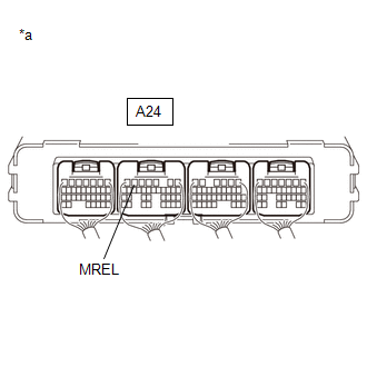
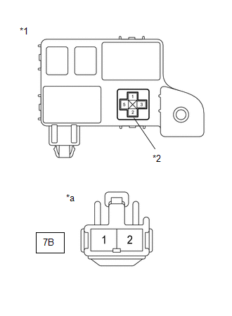
(a) Disconnect the A24 hybrid vehicle control ECU connector.
(b) Remove the IGCT relay from the No. 3 relay block.
(c) Measure the resistance according to the value(s) in the table below.
|
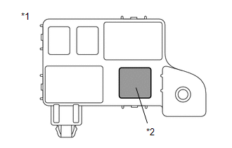
*1 |
No. 3 Relay Block |
*2 |
IGCT Relay Holder |
|
*a |
Rear view of wire harness connector (to Hybrid Vehicle Control ECU) |
- |
- |
Standard Resistance:
|
Tester Connection |
Condition |
Specified Condition |
|---|---|---|
|
A24-6 (MREL) - 1 (IGCT relay holder) |
Always |
Below 1 Ω |
|
A24-6 (MREL) or 1 (IGCT relay holder) - Body ground and other terminals |
Always |
10 kΩ or higher |
(d) Install the IGCT relay.
(e) Reconnect the A24 hybrid vehicle control ECU connector.
| NG |
|
REPAIR OR REPLACE HARNESS OR CONNECTOR |
|
|
11. |
CHECK HARNESS AND CONNECTOR (NO. 3 RELAY BLOCK - BODY GROUND) |
(a) Remove the IGCT relay from the No. 3 relay block.
|
(b) Measure the resistance according to the value(s) in the table below. Standard Resistance:
|
|
(c) Install the IGCT relay.
| OK |
|
| NG |
|
REPAIR OR REPLACE HARNESS OR CONNECTOR |
|
12. |
CHECK HARNESS AND CONNECTOR (NO. 4 RELAY BLOCK - HYBRID VEHICLE CONTROL ECU) |
(a) Remove the PM-IGCT fuse from the No. 4 relay block.
(b) Disconnect the A23 and A24 hybrid vehicle control ECU connectors.
(c) Measure the resistance according to the value(s) in the table below.
|
*1 |
No. 4 Relay Block |
*2 |
PM-IGCT Fuse Holder |
|
*a |
Rear view of wire harness connector (to Hybrid Vehicle Control ECU) |
- |
- |
Standard Resistance:
|
Tester Connection |
Condition |
Specified Condition |
|---|---|---|
|
A24-4 (+B1) or 2 (PM-IGCT fuse holder) - Body ground and other terminals |
Always |
10 kΩ or higher |
|
A23-1 (+B2) or 2 (PM-IGCT fuse holder) - Body ground and other terminals |
Always |
10 kΩ or higher |
(d) Reconnect the A23 and A24 hybrid vehicle control ECU connectors.
(e) Install the PM-IGCT fuse.
| OK |
|
REPLACE FUSE (PM-IGCT) |
| NG |
|
|
13. |
CHECK HARNESS AND CONNECTOR (FUSIBLE LINK BLOCK ASSEMBLY - NO. 3 RELAY BLOCK) |
(a) Disconnect the 7B fusible link block assembly connector.
(b) Remove the IGCT relay from the No. 3 relay block.
|
(c) Measure the resistance according to the value(s) in the table below. Standard Resistance:
|
|
(d) Install the IGCT relay.
(e) Reconnect the 7B fusible link block assembly connector.
| NG |
|
|
|
14. |
CHECK HARNESS AND CONNECTOR (NO. 3 RELAY BLOCK - NO. 4 RELAY BLOCK) |
(a) Remove the IGCT relay from the No. 3 relay block.
(b) Remove the PM-IGCT fuse from the No. 4 relay block.
(c) Measure the resistance according to the value(s) in the table below.
|
*1 |
No. 3 Relay Block |
*2 |
No. 4 Relay Block |
|
*3 |
IGCT Relay Holder |
*4 |
PM-IGCT Fuse Holder |
Standard Resistance:
|
Tester Connection |
Condition |
Specified Condition |
|---|---|---|
|
5 (IGCT relay holder) or 1 (PM-IGCT fuse holder) - Body ground and other terminals |
Always |
10 kΩ or higher |
(d) Install the PM-IGCT fuse.
(e) Install the IGCT relay.
| OK |
|
REPLACE FUSIBLE LINK BLOCK ASSEMBLY (IGCT FUSE) |
| NG |
|
|
15. |
REPAIR OR REPLACE HARNESS OR CONNECTOR |
| NEXT |
|
REPLACE FUSE (PM-IGCT) |
|
16. |
REPAIR OR REPLACE HARNESS OR CONNECTOR |
| NEXT |
|
REPLACE FUSIBLE LINK BLOCK ASSEMBLY (IGCT FUSE) |
|
17. |
REPAIR OR REPLACE HARNESS OR CONNECTOR |
| NEXT |
|
REPLACE FUSIBLE LINK BLOCK ASSEMBLY (IGCT FUSE) |
|
|
|