- Hybrid Battery Current
- Hybrid Battery Voltage
- VL-Voltage before Boosting
- VH-Voltage after Boosting
| Last Modified: 09-10-2025 | 6.11:8.1.0 | Doc ID: RM100000001A0E1 |
| Model Year Start: 2019 | Model: Avalon HV | Prod Date Range: [04/2018 - 08/2020] |
| Title: HYBRID / BATTERY CONTROL: HYBRID CONTROL SYSTEM (for NICKEL METAL HYDRIDE BATTERY): P1C8549; High Voltage Power Resource Internal Electronic Failure; 2019 - 2020 MY Avalon HV [04/2018 - 08/2020] | ||
|
DTC |
P1C8549 |
High Voltage Power Resource Internal Electronic Failure |
DESCRIPTION
The hybrid vehicle control ECU monitors the system internal operation, it will store a DTC and perform fail-safe control if it detects the following malfunction.
|
DTC No. |
Detection Item |
DTC Detection Condition |
Trouble Area |
MIL |
Warning Indicate |
|---|---|---|---|---|---|
|
P1C8549 |
High Voltage Power Resource Internal Electronic Failure |
Battery overcurrent or overload current occurs due to a malfunction in the high-voltage circuit between the hybrid system, battery and inverter. (1 trip detection logic) |
|
Does not come on |
Master Warning Light: Comes on |
Related Data List
|
DTC No. |
Data List |
|---|---|
|
P1C8549 |
|
CONFIRMATION DRIVING PATTERN
HINT:
After repair has been completed, clear the DTC and then check that the vehicle has returned to normal by performing the following All Readiness check procedure.
Click here
![2019 - 2020 MY Avalon HV [04/2018 - 08/2020]; HYBRID / BATTERY CONTROL: HYBRID CONTROL SYSTEM (for NICKEL METAL HYDRIDE BATTERY): UTILITY](/t3Portal/stylegraphics/info.gif)
- Connect the Techstream to the DLC3.
- Turn the power switch on (IG) and turn the Techstream on.
- Clear the DTCs (even if no DTCs are stored, perform the clear DTC procedure).
- Turn the power switch off and wait for 2 minutes or more.
- Turn the power switch on (IG) and turn the Techstream on.
- Drive the vehicle for approximately 10 minutes according to the freeze frame data items "Vehicle Speed", "Accelerator Position" and "Hybrid Battery Current".
- Enter the following menus: Powertrain / Hybrid Control / Utility / All Readiness.
-
Check the DTC judgment result.
HINT:
- If the judgment result shows NORMAL, the system is normal.
- If the judgment result shows ABNORMAL, the system has a malfunction.
- If the judgment result shows INCOMPLETE or N/A, perform driving pattern again.
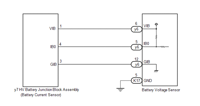
WIRING DIAGRAM
CAUTION / NOTICE / HINT
CAUTION:
-
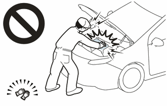
Before the following operations are conducted, take precautions to prevent electric shock by turning the power switch off, wearing insulated gloves, and removing the service plug grip from HV battery.
- Inspecting the high-voltage system
- Disconnecting the low voltage connector of the inverter with converter assembly
- Disconnecting the low voltage connector of the HV battery
-
To prevent electric shock, make sure to remove the service plug grip to cut off the high voltage circuit before servicing the vehicle.
-
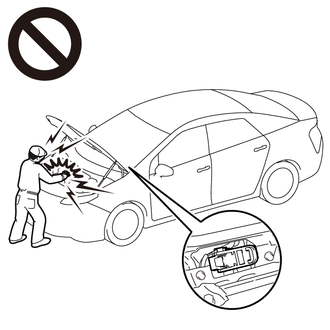
After removing the service plug grip from the HV battery, put it in your pocket to prevent other technicians from accidentally reconnecting it while you are working on the high-voltage system.
-
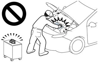
After removing the service plug grip, wait for at least 10 minutes before touching any of the high-voltage connectors or terminals. After waiting for 10 minutes, check the voltage at the terminals in the inspection point in the inverter with converter assembly. The voltage should be 0 V before beginning work.
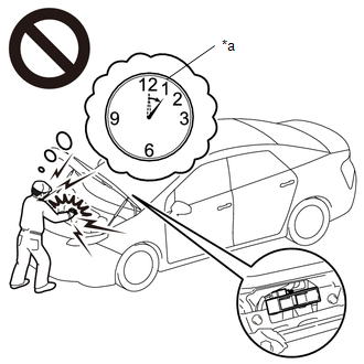
*a
Without waiting for 10 minutes
Click here
HINT:
Waiting for at least 10 minutes is required to discharge the high-voltage capacitor inside the inverter with converter assembly.
NOTICE:
After turning the power switch off, waiting time may be required before disconnecting the cable from the negative (-) auxiliary battery terminal. Therefore, make sure to read the disconnecting the cable from the negative (-) auxiliary battery terminal notices before proceeding with work.
Click here
PROCEDURE
PROCEDURE
|
1. |
CHECK DTC OUTPUT (HYBRID CONTROL) |
(a) Connect the Techstream to the DLC3.
(b) Turn the power switch on (IG).
(c) Enter the following menus: Powertrain / Hybrid Control / Trouble Codes.
(d) Check for DTCs.
Powertrain > Hybrid Control > Trouble Codes
|
Result |
Proceed to |
|---|---|
|
P1C8549 only is output. |
A |
|
DTCs other than P1C8549 is also output. |
B |
(e) Turn the power switch off.
| B |

|
|

|
2. |
READ VALUE USING TECHSTREAM (HYBRID BATTERY CURRENT) |
(a) Connect the Techstream to the DLC3.
(b) Turn the power switch on (IG).
(c) Enter the following menus: Powertrain / Hybrid Control / Data List / Hybrid Battery Current.
Powertrain > Hybrid Control > Data List
|
Tester Display |
|---|
|
Hybrid Battery Current |
(d) Read the Data List.
Result |
Proceed to |
|---|---|
|
The value of Hybrid Battery Current is between -4 A and 4 A |
A |
|
Other than above |
B |
(e) Turn the power switch off.
| A |
|
| B |
|
|
3. |
CHECK HARNESS AND CONNECTOR (BATTERY VOLTAGE SENSOR - HV BATTERY JUNCTION BLOCK ASSEMBLY) |
CAUTION:
Be sure to wear insulated gloves.
(a) Check that the service plug grip is not installed.
NOTICE:
After removing the service plug grip, do not turn the power switch on (READY), unless instructed by the repair manual because this may cause a malfunction.
(b) Remove the No. 1 HV battery cover panel RH.
Click here
|
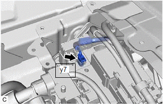
(c) Disconnect the y7 battery current sensor connector. NOTICE: Before disconnecting the connector, check that it is not loose or disconnected. |
|
(d) Remove the No. 1 hybrid battery exhaust duct.
Click here
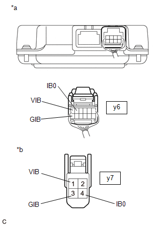
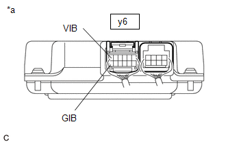
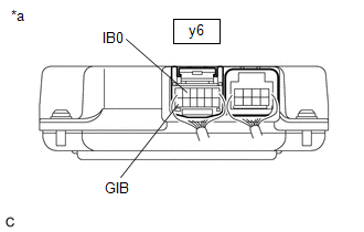
(e) Disconnect the y6 battery voltage sensor connector.
NOTICE:
Before disconnecting the connector, check that it is not loose or disconnected.
|
(f) Measure the resistance according to the value(s) in the tables below. Standard Resistance (Check for Open):
Standard Resistance (Check for Short):
HINT: As the battery harness is not available as a supply part, if the harness cannot be repaired, replace the HV battery. |
|
(g) Reconnect the y6 battery voltage sensor connector.
(h) Install the No. 1 hybrid battery exhaust duct.
(i) Reconnect the y7 battery current sensor connector.
(j) Install the No. 1 HV battery cover panel RH.
| NG |
|
|
|
4. |
CHECK HV BATTERY JUNCTION BLOCK ASSEMBLY (BATTERY CURRENT SENSOR (IB)) |
CAUTION:
Be sure to wear insulated gloves.
(a) Check that the service plug grip is not installed.
NOTICE:
After removing the service plug grip, do not turn the power switch on (READY), unless instructed by the repair manual because this may cause a malfunction.
(b) Remove the No. 1 hybrid battery exhaust duct.
Click here
(c) Connect the cable to the negative (-) auxiliary battery terminal.
(d) Turn the power switch on (IG).
|
(e) Using a toyota electrical tester set to 40 V, measure the VIB voltage according to the value(s) in the table below.
NOTICE:
|
|
|
(f) Using a toyota electrical tester set to 4 V, measure the IB0 voltage according to the value(s) in the table below.
NOTICE: Be sure to set the toyota electrical tester to 4 V when performing this test. |
|
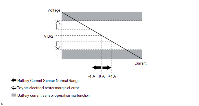
(g) Compare the measured values of the IB0 terminal voltage and VIB terminal voltage using the following formula:
|
IB0 voltage - VIB Voltage / 2 = less than 0.081 V |
|
IB0 voltage - VIB Voltage / 2 = -0.081 V or higher |
|
Result |
Proceed to |
|---|---|
|
Within the specified range above |
A |
|
Other than above |
B |
(h) Turn the power switch off.
(i) Disconnect the cable from the negative (-) auxiliary battery terminal.
(j) Install the No. 1 hybrid battery exhaust duct.
HINT:
When the power switch is on (IG) the actual current will be approximately 0 A. The following graph shows the relation of the actual output voltage of the battery current sensor terminal IB0 and actual current used for DTC judgment.
| B |
|
|
|
5. |
REPLACE BATTERY VOLTAGE SENSOR |
Click here
|
|
6. |
SIMULATION TEST |
(a) Connect the Techstream to the DLC3.
(b) Turn the power switch on (IG).
(c) Enter the following menus: Powertrain / Hybrid Control / Trouble Codes.
(d) Clear the DTCs and freeze frame data.
Powertrain > Hybrid Control > Clear DTCs
(e) Drive the vehicle on urban roads for approximately 10 minutes.
(f) Turn the power switch off and wait for 2 minutes or more.
(g) Turn the power switch on (IG) and wait for 30 seconds or more.
|
|
7. |
RECONFIRM DTC OUTPUT (HYBRID CONTROL) |
(a) Connect the Techstream to the DLC3.
(b) Turn the power switch on (IG).
(c) Enter the following menus: Powertrain / Hybrid Control / Trouble Codes.
(d) Read output DTCs.
Powertrain > Hybrid Control > Trouble Codes
|
Result |
Proceed to |
|---|---|
|
DTCs are not output |
A |
|
P1C8549 is output |
B |
(e) Turn the power switch off.
| A |
|
END |
| B |
|
|
|
|