| Last Modified: 08-21-2023 | 6.11:8.1.0 | Doc ID: RM1000000019XO1 |
| Model Year Start: 2019 | Model: Avalon | Prod Date Range: [04/2018 - ] |
| Title: HEATING / AIR CONDITIONING: AIR CONDITIONING SYSTEM (for Gasoline Model): B14B2; Lost Communication with Front Panel LIN; 2019 - 2022 MY Avalon [04/2018 - ] | ||
|
DTC |
B14B2 |
Lost Communication with Front Panel LIN |
DESCRIPTION
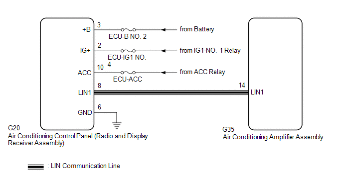
The air conditioning control panel (radio and display receiver assembly) communicates with the air conditioning amplifier assembly via LIN communication.
If a malfunction occurs in the LIN communication system, the air conditioning amplifier assembly will not operate, even if the air conditioning control panel (radio and display receiver assembly) is operated.
|
DTC No. |
Detection Item |
DTC Detection Condition |
Trouble Area |
Memory |
|---|---|---|---|---|
|
B14B2 |
Lost Communication with Front Panel LIN |
Lost communication with air conditioning control assembly |
|
Memorized (10 sec. or more)* |
- *: The air conditioning amplifier assembly stores this DTC if the malfunction has occurred for the period of time indicated in the brackets.
WIRING DIAGRAM
CAUTION / NOTICE / HINT
NOTICE:
Inspect the fuses for circuits related to this system before performing the following procedure.
PROCEDURE
|
1. |
CHECK HARNESS AND CONNECTOR (AIR CONDITIONING CONTROL PANEL (RADIO AND DISPLAY RECEIVER ASSEMBLY) - POWER SOURCE AND BODY GROUND) |
(a) Disconnect the G20 air conditioning control panel (radio and display receiver assembly) connector.
(b) Measure the voltage and resistance according to the value(s) in the table below.
Standard Voltage:
|
Tester Connection |
Condition |
Specified Condition |
|---|---|---|
|
G20-3 (+B) - Body ground |
Engine switch off |
11 to 14 V |
|
G20-2 (IG+) - Body ground |
Engine switch on (IG) |
11 to 14 V |
|
G20-10 (ACC) - Body ground |
Engine switch on (ACC) |
11 to 14 V |
Standard Resistance:
|
Tester Connection |
Condition |
Specified Condition |
|---|---|---|
|
G20-6 (GND) - Body ground |
Always |
Below 1 Ω |
| NG |

|
REPAIR OR REPLACE HARNESS OR CONNECTOR |
|

|
2. |
CHECK HARNESS AND CONNECTOR (AIR CONDITIONING CONTROL PANEL (RADIO AND DISPLAY RECEIVER ASSEMBLY) - AIR CONDITIONING AMPLIFIER ASSEMBLY) |
(a) Disconnect the G35 air conditioning amplifier assembly connector.
(b) Measure the resistance according to the value(s) in the table below.
Standard Resistance:
|
Tester Connection |
Condition |
Specified Condition |
|---|---|---|
|
G20-8 (LIN1) - G35-14 (LIN1) |
Always |
Below 1 Ω |
|
G20-8 (LIN1) or G35-14 (LIN1) - Other terminals and body ground |
Always |
10 kΩ or higher |
| NG |
|
REPAIR OR REPLACE HARNESS OR CONNECTOR |
|
|
3. |
INSPECT AIR CONDITIONING AMPLIFIER ASSEMBLY |
(a) Connect the G35 air conditioning amplifier assembly connector.
(b) Turn the engine switch on (IG).
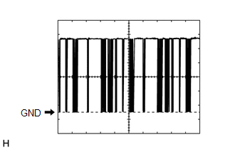
(c) Using an oscilloscope, check the waveform.
|
Item |
Content |
|---|---|
|
Terminal No. |
G35-14 (LIN1) - Body ground |
|
Tool Setting |
2 V/DIV., 20 ms./DIV. |
|
Condition |
Engine switch on (IG) |
OK:
Waveform is similar to that shown in the illustration.
| NG |
|
REPLACE AIR CONDITIONING AMPLIFIER ASSEMBLY
|
![2019 - 2020 MY Avalon Avalon HV [04/2018 - 08/2020]; HEATING / AIR CONDITIONING: AIR CONDITIONING AMPLIFIER: REMOVAL](/t3Portal/stylegraphics/info.gif)
|
|
4. |
INSPECT AIR CONDITIONING CONTROL PANEL (RADIO AND DISPLAY RECEIVER ASSEMBLY) |
|
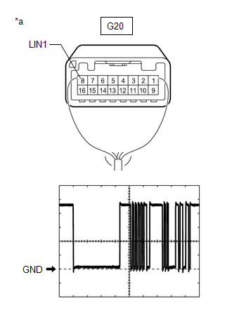
*a |
Component with harness connected (Air Conditioning Control Panel (Radio and Display Receiver Assembly)) |
(a) Connect the G20 air conditioning control panel (radio and display receiver assembly) connector.
(b) Turn the engine switch on (IG).
(c) Using an oscilloscope, check the waveform.
|
Item |
Content |
|---|---|
|
Terminal No. |
G20-8 (LIN1) - Body ground |
|
Tool Setting |
2 V/DIV., 20 ms./DIV. |
|
Condition |
Engine switch on (IG) |
OK:
Waveform is similar to that shown in the illustration.
| OK |
|
REPLACE AIR CONDITIONING AMPLIFIER ASSEMBLY
|
| NG |
|
REPLACE AIR CONDITIONING CONTROL PANEL (RADIO & DISPLAY RECEIVER ASSEMBLY) |
|
|
|