| 
                     
                        | Last Modified: 08-21-2023 | 6.11:8.1.0 | Doc ID: RM1000000019H86 |  
                        | Model Year Start: 2019 | Model: Avalon HV | Prod Date Range: [04/2018 -                    
                                       ] |  
                        | Title: BRAKE SYSTEM (OTHER): BRAKE BOOSTER PUMP(for HV Model): INSTALLATION; 2019 - 2022 MY Avalon HV [04/2018 -        ] |  INSTALLATIONPROCEDURE
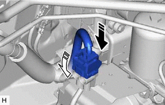
1. INSTALL NO. 2 BRAKE ACTUATOR HOSE (a) Install the No. 2 brake actuator hose to the brake booster pump assembly and slide the clip to secure it.   
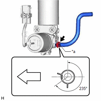


                           | *a | Identification Mark |  
                           |   | Front of the vehicle |  
                     NOTICE: 
                        
Make sure to connect the No. 2 brake actuator hose with its identification mark facing the front of the vehicle.
Install the clip within the range shown in the illustration.
 2. INSTALL BRAKE BOOSTER PUMP ASSEMBLY 
                     
                        
                           | (a) Install the 2 brake booster pump collars and 2 brake booster pump bushings to the brake booster pump assembly as shown in the illustration. HINT: Perform this procedure only when replacement of the brake booster pump collars or brake booster pump bushings is necessary. | 
                                 
                                    |   |  
                                    | 


                                                | *1 | Brake Booster Pump Collar |  
                                                | *2 | Brake Booster Pump Bushing |  |  |  
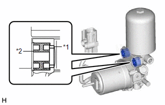
(b) Install the brake booster pump assembly, brake booster pump bushing and brake actuator case collar to the brake actuator bracket assembly as shown in the illustration.   
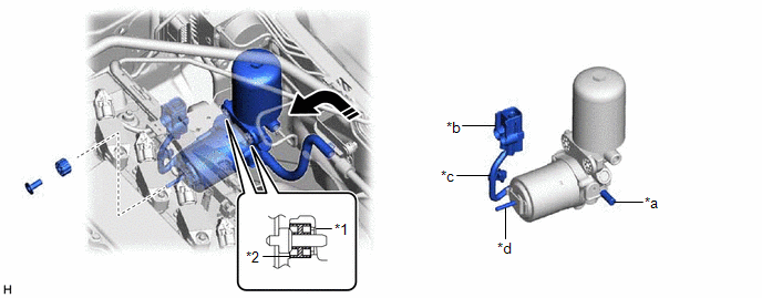


                           | *1 | Brake Booster Pump Collar | *2 | Brake Booster Pump Bushing |  
                           | *a | Union | *b | Connector |  
                           | *c | Wire Harness | *d | Stud |  
                           |   | Install in this Direction | - | - |  
                     NOTICE: 
                        
Be careful not to allow brake fluid to enter the connector.
Do not apply excessive force to the brake lines.
When installing the brake booster pump assembly to the brake actuator bracket assembly, confirm that the 2 brake booster pump bushings and 2 brake booster pump collars are installed to the brake booster pump assembly.
Do not drop the brake booster pump assembly when carrying it.
If installing a new brake booster pump assembly, do not remove the hole plugs before connecting the brake lines because the brake booster pump assembly is filled with brake fluid.
Do not carry the brake booster pump assembly by the parts shown in the illustration.
 (c) Install the nut. Torque:  6.5 N·m {66 kgf·cm, 58 in·lbf} 
                     
                        
                           | (d) Engage the claw and clamp to install the brake booster pump assembly wire harness to the brake actuator bracket assembly. NOTICE: Engage the claw and clamp in the order shown in the illustration. |  |  
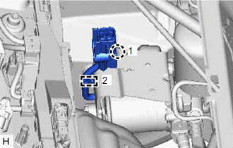
(e) Connect the connector to the brake booster pump assembly and lock the lock lever as shown in the illustration.   


                           |   | Connect the connector |  
                           |   | Lock the lock lever |  
                     NOTICE: 
                        
Make sure that the connector is locked securely.
Make sure that the connector can be connected smoothly.
Do not allow water, oil or dirt to enter the connector.
 3. CONNECT ACCUMULATOR TO BRAKE MASTER CYLINDER TUBE 
                     
                        
                           | (a) Using a union nut wrench, connect the accumulator to brake master cylinder tube to the brake booster pump assembly. Torque:  Specified tightening torque :   15.2 N·m {155 kgf·cm, 11 ft·lbf} 
                                 NOTICE: 
                                    
Do not kink or damage the accumulator to brake master cylinder tube.
Do not allow the accumulator to brake master cylinder tube to twist or interfere with other parts or the vehicle body during tightening.
Do not allow any foreign matter such as dirt or dust to enter the accumulator to brake master cylinder tube from the connecting parts.
 | 
                                 
                                    |   |  
                                    | 


                                                | *a | Torque Wrench Fulcrum Length |  
                                                | *b | Union Nut Wrench |  |  |  
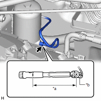
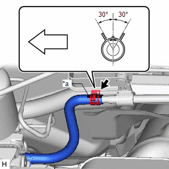
4. CONNECT NO. 2 BRAKE ACTUATOR HOSE (a) Connect the No. 2 brake actuator hose to the No. 1 brake actuator tube and slide the clip to secure it.   


                           | *a | Identification Mark |  
                           |   | Front of the vehicle |  
                     NOTICE: 
                        
When connecting the No. 2 brake actuator hose, face the identification mark up.
Install the clip within the range shown in the illustration.
 5. BLEED NO. 1 BRAKE ACTUATOR TUBE Click here
                        
                           
                              ![2019 - 2022 MY Avalon HV [04/2018 -        ]; BRAKE SYSTEM (OTHER): BRAKE BOOSTER (for HV Model): INSTALLATION+](/t3Portal/stylegraphics/info.gif)  6. FILL RESERVOIR WITH BRAKE FLUID 7. CONNECT CABLE TO NEGATIVE AUXILIARY BATTERY TERMINAL Click here
                        
                           
                              ![2019 - 2022 MY Avalon HV [04/2018 -        ]; MAINTENANCE: A25A-FXS AUXILIARY BATTERY: INSTALLATION+](/t3Portal/stylegraphics/info.gif)  8. BLEED BRAKE SYSTEM Click here
                        
                           
                              ![2019 - 2022 MY Avalon HV [04/2018 -        ]; BRAKE SYSTEM (OTHER): BRAKE FLUID (for HV Model): BLEEDING+](/t3Portal/stylegraphics/info.gif)  9. INSTALL NO. 1 ENGINE COVER SUB-ASSEMBLY Click here
                        
                           
                              ![2019 - 2022 MY Avalon HV [04/2018 -        ]; A25A-FXS (ENGINE MECHANICAL): ENGINE ASSEMBLY: INSTALLATION+](/t3Portal/stylegraphics/info.gif)  10. INSTALL FRONT CENTER UPPER SUSPENSION BRACE SUB-ASSEMBLY Click here
                        
                           
                              ![2019 - 2022 MY Avalon HV [04/2018 -        ]; BRAKE SYSTEM (OTHER): BRAKE BOOSTER (for HV Model): INSTALLATION+](/t3Portal/stylegraphics/info.gif)  11. INSTALL COWL TOP VENTILATOR LOUVER SUB-ASSEMBLY Click here
                        
                           
                              ![2019 - 2022 MY Avalon Avalon HV [04/2018 -        ]; WIPER / WASHER: FRONT WIPER MOTOR: INSTALLATION+](/t3Portal/stylegraphics/info.gif)  |