| Last Modified: 08-21-2023 | 6.11:8.1.0 | Doc ID: RM1000000019H84 |
| Model Year Start: 2019 | Model: Avalon HV | Prod Date Range: [04/2018 - ] |
| Title: BRAKE SYSTEM (OTHER): BRAKE BOOSTER (for HV Model): INSTALLATION; 2019 - 2022 MY Avalon HV [04/2018 - ] | ||
INSTALLATION
PROCEDURE
1. INSTALL BRAKE MASTER CYLINDER GASKET
(a) Install a new brake master cylinder gasket to the brake booster with master cylinder assembly.
2. INSTALL BRAKE BOOSTER WITH MASTER CYLINDER ASSEMBLY
|
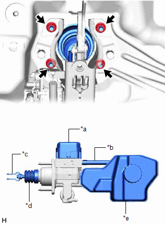
(a) Install the brake booster with master cylinder assembly with the 4 nuts. Torque: 12.8 N·m {131 kgf·cm, 9 ft·lbf} NOTICE:
|
|
3. INSTALL PUSH ROD PIN
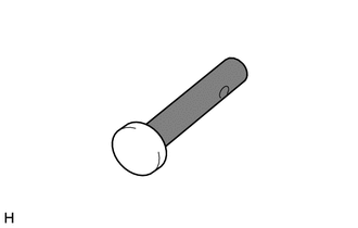
(a) Apply lithium soap base glycol grease to the push rod pin.

|
Lithium Soap Base Glycol Grease |
|
(b) Connect the brake master cylinder push rod clevis to the brake pedal support assembly with the push rod pin, and install a new clip as shown in the illustration. HINT: The push rod pin can be installed in either direction. |
|
4. CONNECT BRAKE LINE
|
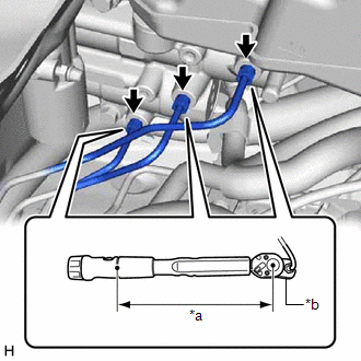
(a) Using a union nut wrench, connect the 3 brake lines to the brake booster with master cylinder assembly. Torque: Specified tightening torque : 15.2 N·m {155 kgf·cm, 11 ft·lbf} NOTICE:
HINT:
|
|
5. CONNECT NO. 1 BRAKE ACTUATOR HOSE
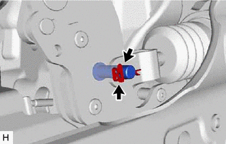
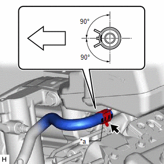
(a) Connect the No. 1 brake actuator hose to the brake booster with master cylinder assembly and slide the clip to secure it.
|
*a |
Identification Mark |

|
Front of the vehicle |
NOTICE:
- Make sure to connect the No. 1 brake actuator hose with its identification mark facing the front of the vehicle.
- Install the clip within the range shown in the illustration.
6. CONNECT ENGINE ROOM MAIN WIRE
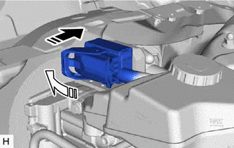
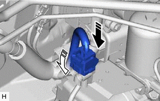
(a) Connect the connector to the brake booster with master cylinder assembly and lock the lock lever as shown in the illustration.

|
Connect the connector |

|
Lock the lock lever |
NOTICE:
- Make sure that the connector is locked securely.
- Make sure that the connector can be connected smoothly.
- Do not allow water, oil or dirt to enter the connector.
|
(b) Connect the connector to the brake booster with master cylinder assembly. |
|
7. BLEED NO. 1 BRAKE ACTUATOR TUBE
NOTICE:
Make sure to bleed the air from the No. 1 brake actuator tube. If the air remains in the No. 1 brake actuator tube, the air will enter the brake booster pump assembly and may damage the brake booster pump assembly.
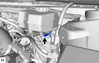
(a) Remove the brake master cylinder reservoir filler cap assembly.
(b) Add brake fluid to the reservoir until the fluid level is between the MAX and MIN lines on the brake fluid reservoir.
Brake Fluid:
SAE J1703 or FMVSS No. 116 DOT3
SAE J1704 or FMVSS No. 116 DOT4
|
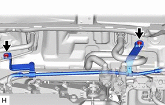
(c) Remove the 2 nuts to separate the No. 1 brake actuator tube. |
|
|
(d) Set SST to the brake master cylinder reservoir assembly. SST: 09992-00242 SST: 09992-00350 |
|
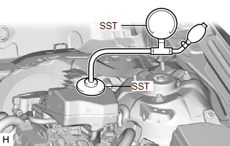
(e) Using SST, increase and then maintain the pressure in the brake master cylinder reservoir assembly for 60 seconds.(*1)
Standard Pressure:
50 to 80 kPa (0.6 to 0.8 kgf/cm2, 7.3 to 11.6 psi)
(f) Release the pressure in the brake master cylinder reservoir assembly and wait for 30 seconds.(*2)
(g) Repeat steps *1 to *2, 3 times.
(h) Remove SST.
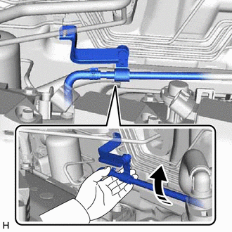
(i) Elevate the No. 1 brake actuator tube for 10 seconds by lifting the No. 1 brake actuator tube as shown in the illustration.(*3)
|
|
Pull up |
NOTICE:
Do not damage the hoses by applying excessive force.
(j) Repeat step *3, 5 times.
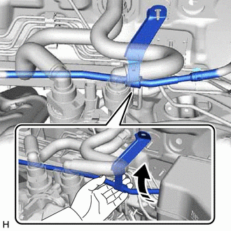
(k) Elevate the No. 1 brake actuator tube for 10 seconds by lifting the No. 1 brake actuator tube as shown in the illustration.(*4)
NOTICE:
Do not damage the hoses by applying excessive force.
|
|
Pull up |
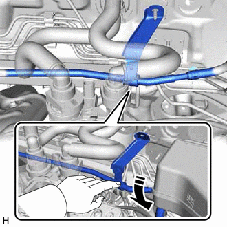
(l) Lower the No. 1 brake actuator tube for 10 seconds as shown in the illustration.(*5)
NOTICE:
Do not damage the hoses by applying excessive force.
|
|
Press down |
(m) Repeat steps *4 to *5, 5 times.
(n) Install the No. 1 brake actuator tube with the 2 nuts.
Torque:
8.5 N·m {87 kgf·cm, 75 in·lbf}
8. CONNECT BRAKE BOOSTER PUMP CONNECTOR
HINT:
Perform this operation only when the accumulator pressure zero down operation could not be performed using the Techstream.
(a) Connect the connector to the brake booster pump assembly and lock the lock lever as shown in the illustration.
|
|
Connect the connector |
|
|
Lock the lock lever |
NOTICE:
- Make sure that the connector is locked securely.
- Make sure that the connector can be connected smoothly.
- Do not allow water, oil or dirt to enter the connector.
9. FILL RESERVOIR WITH BRAKE FLUID
10. CONNECT CABLE TO NEGATIVE AUXILIARY BATTERY TERMINAL
Click here
![2019 - 2022 MY Avalon HV [04/2018 - ]; MAINTENANCE: A25A-FXS AUXILIARY BATTERY: INSTALLATION+](/t3Portal/stylegraphics/info.gif)
11. BLEED BRAKE SYSTEM
Click here
12. INSPECT AND ADJUST BRAKE PEDAL
Click here
13. OBTAIN ZERO POINT OF YAW RATE AND ACCELERATION SENSOR
Click here
14. INSTALL NO. 1 INSTRUMENT PANEL UNDER COVER SUB-ASSEMBLY
Click here
15. INSTALL FRONT CENTER UPPER SUSPENSION BRACE SUB-ASSEMBLY
|
(a) Temporarily install the front center upper suspension brace sub-assembly with the 6 bolts and 4 nuts. |
|
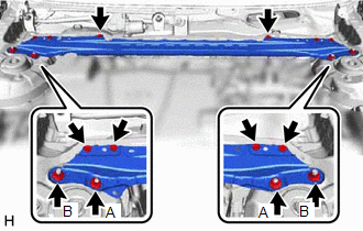
(b) Fully tighten the 2 nuts (A).
Torque:
50 N·m {510 kgf·cm, 37 ft·lbf}
(c) Fully tighten the 6 bolts and 2 nuts (B) to install the front center upper suspension brace sub-assembly.
Torque:
Bolt :
8.9 N·m {91 kgf·cm, 79 in·lbf}
Nut (B) :
39 N·m {398 kgf·cm, 29 ft·lbf}
(d) Engage the 2 clamps to install the wire harness.
(e) Connect the connector.
16. INSTALL COWL TOP VENTILATOR LOUVER SUB-ASSEMBLY
Click here
|
|
|