| Last Modified: 02-14-2025 | 6.11:8.1.0 | Doc ID: RM100000001T5IV |
| Model Year Start: 2021 | Model: Camry HV | Prod Date Range: [10/2020 - ] |
| Title: PARK ASSIST / MONITORING: PANORAMIC VIEW MONITOR SYSTEM: C1683; Side Camera Feedback Malfunction; 2021 - 2024 MY Camry HV [10/2020 - ] | ||
|
DTC |
C1683 |
Side Camera Feedback Malfunction |
DESCRIPTION
This DTC is stored if the television camera controller judges as a result of its self check that a synchronization problem is occurring in the image signal sent from the passenger side television camera assembly to the television camera controller.
|
DTC No. |
Detection Item |
DTC Detection Condition |
Trouble Area |
|---|---|---|---|
|
C1683 |
Side Camera Feedback Malfunction |
Side camera feedback malfunction |
|
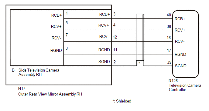
WIRING DIAGRAM
CAUTION / NOTICE / HINT
NOTICE:
-
When "!" is displayed on the radio and display receiver assembly after the cable is disconnected from the negative (-) auxiliary battery terminal, correct the steering angle neutral point.
Click here
![2021 - 2024 MY Camry HV [10/2020 - ]; PARK ASSIST / MONITORING: PANORAMIC VIEW MONITOR SYSTEM: INITIALIZATION](/t3Portal/stylegraphics/info.gif)
-
Depending on the parts that are replaced or operations that are performed during vehicle inspection or maintenance, calibration of other systems as well as the panoramic view monitor system may be needed.
Click here
PROCEDURE
|
1. |
CHECK FOR DTC |
(a) Clear the DTCs.
Chassis > Circumference Monitoring Camera Control Module > Clear DTCs
(b) Check for DTCs.
Chassis > Circumference Monitoring Camera Control Module > Trouble Codes
OK:
DTC C1683 is not output.
| OK |

|
USE SIMULATION METHOD TO CHECK
|
|

|
2. |
CHECK HARNESS AND CONNECTOR (TELEVISION CAMERA CONTROLLER - OUTER REAR VIEW MIRROR ASSEMBLY RH) |
(a) Disconnect the R126 television camera controller connector.
(b) Disconnect the N17 outer rear view mirror assembly RH connector.
(c) Measure the resistance according to the value(s) in the table below.
Standard Resistance:
|
Tester Connection |
Condition |
Specified Condition |
|---|---|---|
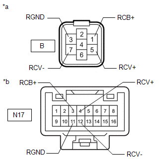
|
R126-40 (RCB+) - N17-3 (RCB+) |
Always |
Below 1 Ω |
|
R126-38 (RCV+) - N17-4 (RCV+) |
Always |
Below 1 Ω |
|
R126-16 (RCV-) - N17-12 (RCV-) |
Always |
Below 1 Ω |
|
R126-17 (RGND) - N17-11 (RGND) |
Always |
Below 1 Ω |
|
R126-40 (RCB+) or N17-3 (RCB+) - Body ground |
Always |
10 kΩ or higher |
|
R126-38 (RCV+) or N17-4 (RCV+) - Body ground |
Always |
10 kΩ or higher |
|
R126-16 (RCV-) or N17-12 (RCV-) - Body ground |
Always |
10 kΩ or higher |
|
R126-17 (RGND) or N17-11 (RGND) - Body ground |
Always |
10 kΩ or higher |
|
R126-39 (RGND) or N17-2 (SGND) - Body ground |
Always |
10 kΩ or higher |
| NG |
|
REPAIR OR REPLACE HARNESS OR CONNECTOR |
|
|
3. |
CHECK TELEVISION CAMERA CONTROLLER (RCV-, RGND) |
|
(a) Disconnect the R126 television camera controller connector. |
|
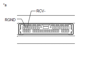
(b) Measure the resistance according to the value(s) in the table below.
Standard Resistance:
|
Tester Connection |
Condition |
Specified Condition |
|---|---|---|
|
17 (RGND) - Body ground |
Always |
Below 1 Ω |
|
16 (RCV-) - Body ground |
Always |
Below 1 Ω |
| NG |
|
|
|
4. |
CHECK TELEVISION CAMERA CONTROLLER (RCB+, RGND) |
|
(a) Measure the resistance according to the value(s) in the table below. Standard Resistance:
|
|
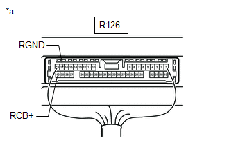
(b) Measure the voltage according to the value(s) in the table below.
Standard Voltage:
|
Tester Connection |
Switch Condition |
Specified Condition |
|---|---|---|
|
R126-40 (RCB+) - R126-17 (RGND) |
Ignition switch ON |
5.5 to 7.05 V |
|
R126-40 (RCB+) - R126-17 (RGND) |
Ignition switch off |
Below 1 V |
| NG |
|
|
|
5. |
CHECK SIDE TELEVISION CAMERA ASSEMBLY RH (RCV+, RGND) |
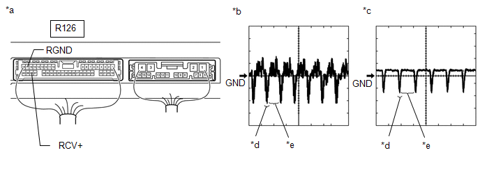
(a) Using an oscilloscope, check the waveform of the side television camera assembly RH.
HINT:
A waterproof connector is used for the side television camera assembly RH. Therefore, inspect the waveform at the television camera controller with the connector connected.
|
*a |
Component with harness connected (Television Camera Controller) |
*b |
Waveform 1 (camera lens not covered, displaying an image) |
|
*c |
Waveform 2 (camera lens covered, blacking out the screen) |
*d |
Synchronization Signal |
|
*e |
Video Waveform |
- |
- |
HINT:
- The video waveform changes according to the image sent by the side television camera assembly RH.
- The video waveform is constantly output when the ignition switch is ACC.
Measurement Condition
|
Item |
Content |
|---|---|
|
Tester Connection |
R126-38 (RCV+) - R126-17 (RGND) |
|
Tool Setting |
200 mV/DIV., 50 μsec./DIV. |
|
Condition |
Ignition switch ON, panoramic view monitor switch on |
OK:
Waveform is similar to that shown in illustration.
| OK |
|
|
|
6. |
INSPECT OUTER REAR VIEW MIRROR ASSEMBLY RH |
|
(a) Disconnect the side television camera assembly RH connector. |
|
(b) Disconnect the outer rear view mirror assembly RH connector.
(c) Measure the resistance according to the value(s) in the table below.
Standard Resistance:
|
Tester Connection |
Condition |
Specified Condition |
|---|---|---|
|
B-1 (RCB+) - N17-3 (RCB+) |
Always |
Below 1 Ω |
|
B-5 (RCV+) - N17-4 (RCV+) |
Always |
Below 1 Ω |
|
B-7 (RCV-) - N17-12 (RCV-) |
Always |
Below 1 Ω |
|
B-3 (RGND) - N17-11 (RGND) |
Always |
Below 1 Ω |
|
B-1 (RCB+) or N17-3 (RCB+) - Body ground |
Always |
10 kΩ or higher |
|
B-5 (RCV+) or N17-4 (RCV+) - Body ground |
Always |
10 kΩ or higher |
|
B-7 (RCV-) or N17-12 (RCV-) - Body ground |
Always |
10 kΩ or higher |
|
B-3 (RGND) or N17-11 (RGND) - Body ground |
Always |
10 kΩ or higher |
| NG |
|
|
|
7. |
REPLACE SIDE TELEVISION CAMERA ASSEMBLY RH |
(a) Replace the side television camera assembly RH with a new or normally functioning one.
Click here
|
|
8. |
CHECK FOR DTC |
(a) Clear the DTCs.
Chassis > Circumference Monitoring Camera Control Module > Clear DTCs
(b) Check for DTCs.
Chassis > Circumference Monitoring Camera Control Module > Trouble Codes
OK:
DTC C1683 is not output.
| OK |
|
END (SIDE TELEVISION CAMERA ASSEMBLY RH IS DEFECTIVE) |
| NG |
|
|
|
|