| Last Modified: 02-14-2025 | 6.11:8.1.0 | Doc ID: RM100000001T5IU |
| Model Year Start: 2021 | Model: Camry HV | Prod Date Range: [10/2020 - ] |
| Title: PARK ASSIST / MONITORING: PANORAMIC VIEW MONITOR SYSTEM: C1682; Front Camera Current Malfunction; 2021 - 2024 MY Camry HV [10/2020 - ] | ||
|
DTC |
C1682 |
Front Camera Current Malfunction |
DESCRIPTION
DTC C1682 is stored if the television camera controller judges as a result of its self check that there is a problem with the current supplied from the front television camera assembly connected to the television camera controller.
|
DTC No. |
Detection Item |
DTC Detection Condition |
Trouble Area |
|---|---|---|---|
|
C1682 |
Front Camera Current Malfunction |
Open or short in the front television camera signal circuit |
|
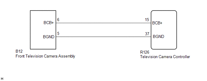
WIRING DIAGRAM
CAUTION / NOTICE / HINT
NOTICE:
-
When "!" is displayed on the radio and display receiver assembly after the cable is disconnected from the negative (-) auxiliary battery terminal, correct the steering angle neutral point.
Click here
![2021 - 2024 MY Camry HV [10/2020 - ]; PARK ASSIST / MONITORING: PANORAMIC VIEW MONITOR SYSTEM: INITIALIZATION](/t3Portal/stylegraphics/info.gif)
-
Depending on the parts that are replaced or operations that are performed during vehicle inspection or maintenance, calibration of other systems as well as the panoramic view monitor system may be needed.
Click here
PROCEDURE
|
1. |
CHECK HARNESS AND CONNECTOR (TELEVISION CAMERA CONTROLLER - FRONT TELEVISION CAMERA ASSEMBLY) |
(a) Disconnect the R126 television camera controller connector.
(b) Disconnect the B12 front television camera assembly connector.
(c) Measure the resistance according to the value(s) in the table below.
Standard Resistance:
|
Tester Connection |
Condition |
Specified Condition |
|---|---|---|
|
R126-15 (BCB+) - B12-6 (BCB+) |
Always |
Below 1 Ω |
|
R126-37 (BGND) - B12-5 (BGND) |
Always |
Below 1 Ω |
|
R126-15 (BCB+) or B12-6 (BCB+) - Body ground |
Always |
10 kΩ or higher |
|
R126-37 (BGND) or B12-5 (BGND) - Body ground |
Always |
10 kΩ or higher |
| NG |

|
REPAIR OR REPLACE HARNESS OR CONNECTOR |
|

|
2. |
CHECK TELEVISION CAMERA CONTROLLER (BCB+, BGND) |
|
(a) Remove the television camera controller with the connector still connected. |
|
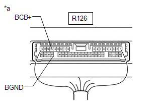
(b) Measure the resistance according to the value(s) in the table below.
Standard Resistance:
|
Tester Connection |
Condition |
Specified Condition |
|---|---|---|
|
R126-37 (BGND) - Body ground |
Always |
Below 1 Ω |
(c) Measure the voltage according to the value(s) in the table below.
Standard Voltage:
|
Tester Connection |
Condition |
Specified Condition |
|---|---|---|
|
R126-15 (BCB+) - R126-37 (BGND) |
Ignition switch ON |
5.5 to 7.05 V |
|
R126-15 (BCB+) - R126-37 (BGND) |
Ignition switch off |
Below 1 V |
| OK |
|
| NG |
|
|
|
|