| Last Modified: 02-14-2025 | 6.11:8.1.0 | Doc ID: RM100000001T5H3 |
| Model Year Start: 2021 | Model: Camry HV | Prod Date Range: [10/2020 - ] |
| Title: PARK ASSIST / MONITORING: INTUITIVE PARKING ASSIST SYSTEM: Clearance Warning ECU Power Source Circuit; 2021 - 2024 MY Camry HV [10/2020 - ] | ||
|
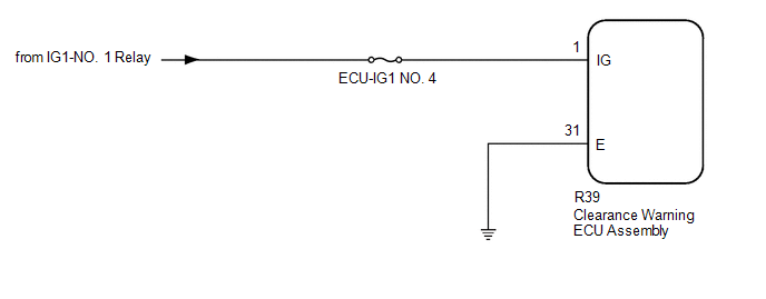
Clearance Warning ECU Power Source Circuit |
DESCRIPTION
This circuit provides power to operate the clearance warning ECU assembly.
WIRING DIAGRAM
CAUTION / NOTICE / HINT
NOTICE:
Inspect the fuses for circuits related to this system before performing the following procedure.
PROCEDURE
|
1. |
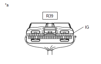
CHECK HARNESS AND CONNECTOR (CLEARANCE WARNING ECU ASSEMBLY POWER SOURCE) |
(a) Disconnect the R39 clearance warning ECU assembly connector.
|
*a |
Front view of wire harness connector (to Clearance Warning ECU Assembly) |
(b) Measure the voltage according to the value(s) in the table below.
Standard Voltage:
|
Tester Connection |
Switch Condition |
Specified Condition |
|---|---|---|
|
R39-1 (IG) - Body ground |
Ignition switch ON |
11 to 14 V |
|
R39-1 (IG) - Body ground |
Ignition switch off |
Below 1 V |
| NG |

|
REPAIR OR REPLACE HARNESS OR CONNECTOR |
|

|
2. |
CHECK HARNESS AND CONNECTOR (CLEARANCE WARNING ECU ASSEMBLY - BODY GROUND) |
(a) Measure the resistance according to the value(s) in the table below.
Standard Resistance:
|
Tester Connection |
Condition |
Specified Condition |
|---|---|---|
|
R39-31 (E) - Body ground |
Always |
Below 1 Ω |
| OK |
|
PROCEED TO NEXT SUSPECTED AREA SHOWN IN PROBLEM SYMPTOMS TABLE |
| NG |
|
REPAIR OR REPLACE HARNESS OR CONNECTOR |
|
|
|