| Last Modified: 02-14-2025 | 6.11:8.1.0 | Doc ID: RM100000001T330 |
| Model Year Start: 2021 | Model: Camry HV | Prod Date Range: [10/2020 - ] |
| Title: PARK ASSIST / MONITORING: PARKING SUPPORT BRAKE SYSTEM: U117787,U117887; Lost Communication with Side Obstacle Detection Control Module "A" (ch2) Missing Message; 2021 - 2024 MY Camry HV [10/2020 - ] | ||
|
DTC |
U117787 |
Lost Communication with Side Obstacle Detection Control Module "A" (ch2) Missing Message |
|
DTC |
U117887 |
Lost Communication with Side Obstacle Detection Control Module "B" (ch2) Missing Message |
DESCRIPTION
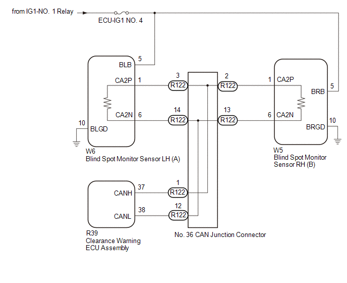
This DTC is output when the clearance warning ECU assembly detects lost communication with the blind spot monitor sensor.
|
DTC No. |
Detection Item |
DTC Detection Condition |
Trouble Area |
Memory |
|---|---|---|---|---|
|
U117787 |
Lost Communication with Side Obstacle Detection Control Module "A" (ch2) Missing Message |
The clearance warning ECU assembly is unable to receive communication from the blind spot monitor sensor LH (A) |
|
○ |
|
U117887 |
Lost Communication with Side Obstacle Detection Control Module "B" (ch2) Missing Message |
The clearance warning ECU assembly is unable to receive communication from the blind spot monitor sensor RH (B) |
|
○ |
WIRING DIAGRAM
CAUTION / NOTICE / HINT
NOTICE:
- Inspect the fuses for circuits related to this system before performing the following procedure.
- Before measuring the resistance of the CAN bus, turn the ignition switch off and leave the vehicle for 1 minute or more without operating the key or any switches, or opening or closing the doors. After that, disconnect the cable from the negative (-) auxiliary battery terminal and leave the vehicle for 1 minute or more before measuring the resistance.
-
After turning the ignition switch off, waiting time may be required before disconnecting the cable from the negative (-) auxiliary battery terminal. Therefore, make sure to read the disconnecting the cable from the negative (-) auxiliary battery terminal notices before proceeding with work.
Click here
![2020 - 2024 MY Camry HV [09/2019 - ]; INTRODUCTION: REPAIR INSTRUCTION: PRECAUTION](/t3Portal/stylegraphics/info.gif)
HINT:
- Operating the ignition switch, any other switches or a door triggers related ECU and sensor communication on the CAN. This communication will cause the resistance value to change.
- Even after DTCs are cleared, if a DTC is stored again after driving the vehicle for a while, the malfunction may be occurring due to vibration of the vehicle. In such a case, wiggling the ECUs or wire harness while performing the inspection below may help determine the cause of the malfunction.
PROCEDURE
|
1. |
CHECK FOR DTC |
(a) Using the GTS, check for parking support brake system DTCs.
Body Electrical > Clearance Warning > Trouble Codes
|
Result |
Proceed to |
|---|---|
|
No DTCs are output |
A |
|
DTC U117787 only is output |
B |
|
DTC U117887 only is output |
C |
|
DTC U117787 and U117887 are output |
D |
| A |

|
USE SIMULATION METHOD TO CHECK
|
| C |
|
| D |
|
|

|
2. |
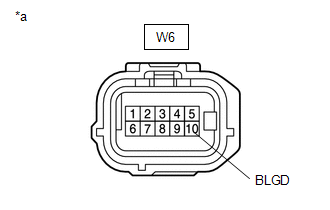
CHECK HARNESS AND CONNECTOR (BLIND SPOT MONITOR SENSOR LH (A) - BODY GROUND) |
|
(a) Disconnect the connector of the blind spot monitor sensor LH (A). |
|
(b) Measure the resistance according to the value(s) in the table below.
Standard Resistance:
|
Tester Connection |
Condition |
Specified Condition |
|---|---|---|
|
W6-10 (BLGD) - Body ground |
Always |
Below 1 Ω |
| NG |
|
REPAIR OR REPLACE HARNESS OR CONNECTOR |
|
|
3. |
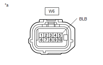
CHECK HARNESS AND CONNECTOR (BLIND SPOT MONITOR SENSOR LH (A) - POWER SOURCE) |
|
(a) Disconnect the connector of the blind spot monitor sensor LH (A). |
|
(b) Measure the voltage according to the value(s) in the table below.
Standard Voltage:
|
Tester Connection |
Switch Condition |
Specified Condition |
|---|---|---|
|
W6-5 (BLB) - Body ground |
Ignition Switch ON |
11 to 14 V |
|
W6-5 (BLB) - Body ground |
Ignition switch off |
Below 1 V |
| OK |
|
| NG |
|
REPAIR OR REPLACE HARNESS OR CONNECTOR |
|
4. |
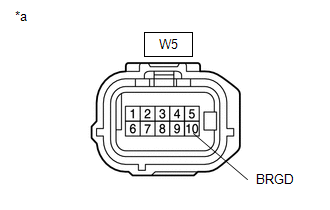
CHECK HARNESS AND CONNECTOR (BLIND SPOT MONITOR SENSOR RH (B) - BODY GROUND) |
|
(a) Disconnect the connector of the blind spot monitor sensor RH (B). |
|
(b) Measure the resistance according to the value(s) in the table below.
Standard Resistance:
|
Tester Connection |
Condition |
Specified Condition |
|---|---|---|
|
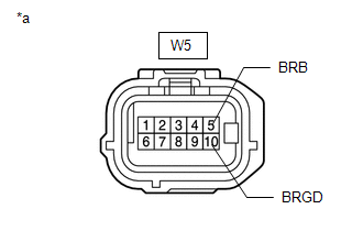
W5-10 (BRGD) - Body ground |
Always |
Below 1 Ω |
| NG |
|
REPAIR OR REPLACE HARNESS OR CONNECTOR |
|
|
5. |
CHECK HARNESS AND CONNECTOR (BLIND SPOT MONITOR SENSOR RH (B) - POWER SOURCE) |
|
(a) Disconnect the connector of the blind spot monitor sensor RH (B). |
|
(b) Measure the voltage according to the value(s) in the table below.
Standard Voltage:
|
Tester Connection |
Switch Condition |
Specified Condition |
|---|---|---|
|
W5-5 (BRB) - Body ground |
Ignition switch ON |
11 to 14 V |
|
W5-5 (BRB) - Body ground |
Ignition switch off |
Below 1 V |
| OK |
|
| NG |
|
REPAIR OR REPLACE HARNESS OR CONNECTOR |
|
6. |
CHECK CAN BUS (CONFIRM PROBLEM SYMPTOMS) |
(a) Turn the ignition switch off.
(b) Disconnect the cable from the negative (-) auxiliary battery terminal.
|
(c) Measure the resistance according to the value(s) in the table below. Standard Resistance:
|
|
|
Result |
Proceed to |
|---|---|
|
OK |
A |
|
NG (open in main line) |
B |
|
NG (short in line) |
C |
|
NG (short to +B or ground) |
D |
| B |
|
| C |
|
| D |
|
|
|
7. |
CLEAR DTCS |
(a) Using the GTS, clear the DTCs.
Body Electrical > Clearance Warning > Clear DTCs
|
|
8. |
CHECK FOR DTC |
(a) Check for DTCs.
Body Electrical > Clearance Warning > Trouble Codes
|
Result |
Proceed to |
|---|---|
|
DTC U117787 and U117887 are output |
A |
|
DTC U117787 and U117887 are not output |
B |
| A |
|
| B |
|
|
9. |
CHECK FOR OPEN IN CAN BUS WIRE (NO. 36 CAN JUNCTION CONNECTOR) |
(a) Disconnect the No. 36 CAN junction connector.
|
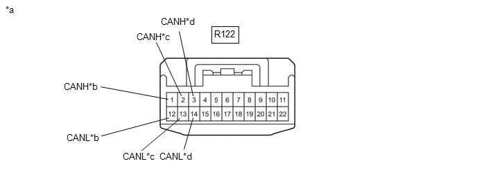
*a |
Front view of wire harness connector (to No. 36 CAN Junction Connector) |
*b |
to Clearance Warning ECU Assembly CAN Wire |
|
*c |
to Blind Spot Monitor Sensor RH (B) CAN Main Wire |
*d |
to Blind Spot Monitor Sensor LH (A) CAN Main Wire |
(b) Measure the resistance according to the value(s) in the table below.
Standard Resistance:
|
Tester Connection |
Condition |
Specified Condition |
|---|---|---|
|
R122-1 (CANH) - R122-12 (CANL) |
Cable disconnected from negative (-) auxiliary battery terminal |
200 Ω or higher |
|
R122-3 (CANH) - R122-14 (CANL) |
Cable disconnected from negative (-) auxiliary battery terminal |
108 to 132 Ω |
|
R122-2 (CANH) - R122-13 (CANL) |
Cable disconnected from negative (-) auxiliary battery terminal |
108 to 132 Ω |
|
Result |
Proceed to |
|---|---|
|
OK |
A |
|
NG (to blind spot monitor sensor LH (A) CAN main wire) |
B |
|
NG (to blind spot monitor sensor RH (B) CAN main wire) |
C |
|
NG (to clearance warning ECU assembly CAN wire) |
D |
| A |
|
REPLACE NO. 36 CAN JUNCTION CONNECTOR |
| C |
|
| D |
|
|
|
10. |
CHECK FOR OPEN IN CAN BUS MAIN WIRE (BLIND SPOT MONITOR SENSOR LH (A)) |
|
(a) Reconnect the R122 No. 36 CAN junction connector. |
|
(b) Disconnect the W6 blind spot monitor sensor LH (A) connector.
(c) Measure the resistance according to the value(s) in the table below.
Standard Resistance:
|
Tester Connection |
Condition |
Specified Condition |
|---|---|---|
|
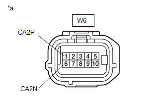
W6-1 (CA2P) - W6-6 (CA2N) |
Cable disconnected from negative (-) auxiliary battery terminal |
108 to 132 Ω |
| OK |
|
| NG |
|
REPAIR OR REPLACE CAN MAIN WIRE OR CONNECTOR (BLIND SPOT MONITOR SENSOR LH (A) - NO. 36 CAN JUNCTION CONNECTOR) |
|
11. |
CHECK FOR OPEN IN CAN BUS MAIN WIRE (BLIND SPOT MONITOR SENSOR RH (B)) |
|
(a) Reconnect the R122 No. 36 CAN junction connector. |
|
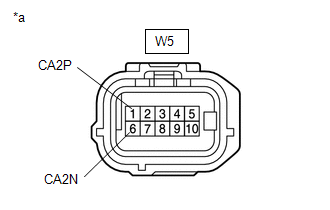
(b) Disconnect the W5 blind spot monitor sensor RH (B) connector.
(c) Measure the resistance according to the value(s) in the table below.
Standard Resistance:
|
Tester Connection |
Condition |
Specified Condition |
|---|---|---|
|
W5-1 (CA2P) - W5-6 (CA2N) |
Cable disconnected from negative (-) auxiliary battery terminal |
108 to 132 Ω |
| OK |
|
| NG |
|
REPAIR OR REPLACE CAN MAIN WIRE OR CONNECTOR (BLIND SPOT MONITOR SENSOR RH (B) - NO. 36 CAN JUNCTION CONNECTOR) |
|
12. |
CHECK FOR OPEN IN CAN BUS WIRE (CLEARANCE WARNING ECU ASSEMBLY) |
|
(a) Reconnect the No. 36 CAN junction connector. |
|

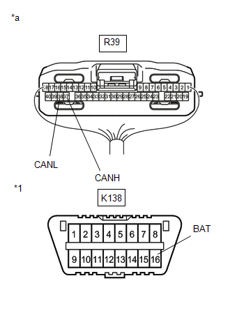
(b) Disconnect the R39 clearance warning ECU assembly connector.
(c) Measure the resistance according to the value(s) in the table below.
Standard Resistance:
|
Tester Connection |
Condition |
Specified Condition |
|---|---|---|
|
R39-37 (CANH) - R39-38 (CANL) |
Cable disconnected from negative (-) auxiliary battery terminal |
54 to 69 Ω |
| OK |
|
| NG |
|
REPAIR OR REPLACE CAN BUS WIRE (CLEARANCE WARNING ECU ASSEMBLY - NO. 36 CAN JUNCTION CONNECTOR) |
|
13. |
CHECK FOR SHORT IN CAN BUS WIRES (NO. 36 CAN JUNCTION CONNECTOR) |
(a) Disconnect the No. 36 CAN junction connector.

|
*a |
Front view of wire harness connector (to No. 36 CAN Junction Connector) |
*b |
to Clearance Warning ECU Assembly CAN Wire |
|
*c |
to Blind Spot Monitor Sensor RH (B) CAN Main Wire |
*d |
to Blind Spot Monitor Sensor LH (A) CAN Main Wire |
(b) Measure the resistance according to the value(s) in the table below.
Standard Resistance:
|
Tester Connection |
Condition |
Specified Condition |
|---|---|---|
|
R122-1 (CANH) - R122-12 (CANL) |
Cable disconnected from negative (-) auxiliary battery terminal |
200 Ω or higher |
|
R122-3 (CANH) - R122-14 (CANL) |
Cable disconnected from negative (-) auxiliary battery terminal |
108 to 132 Ω |
|
R122-2 (CANH) - R122-13 (CANL) |
Cable disconnected from negative (-) auxiliary battery terminal |
108 to 132 Ω |
|
Result |
Proceed to |
|---|---|
|
OK |
A |
|
NG (to blind spot monitor sensor LH (A) CAN main wire) |
B |
|
NG (to blind spot monitor sensor RH (B) CAN main wire) |
C |
|
NG (to clearance warning ECU assembly CAN wire) |
D |
| A |
|
REPLACE NO. 36 CAN JUNCTION CONNECTOR |
| C |
|
| D |
|
|
|
14. |
CHECK FOR SHORT IN CAN BUS WIRES (BLIND SPOT MONITOR SENSOR LH (A)) |
|
(a) Reconnect the R122 No.36 CAN junction connector. |
|
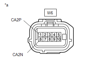
(b) Disconnect the W6 blind spot monitor sensor LH (A) connector.
(c) Measure the resistance according to the value(s) in the table below.
Standard Resistance:
|
Tester Connection |
Condition |
Specified Condition |
|---|---|---|
|
W6-1 (CA2P) - W6-6 (CA2N) |
Cable disconnected from negative (-) auxiliary battery terminal |
108 to 132 Ω |
| OK |
|
| NG |
|
REPAIR OR REPLACE CAN MAIN WIRE OR CONNECTOR (BLIND SPOT MONITOR SENSOR LH (A) - NO. 36 CAN JUNCTION CONNECTOR) |
|
15. |
CHECK FOR SHORT IN CAN BUS WIRES (BLIND SPOT MONITOR SENSOR RH (B)) |
|
(a) Reconnect the R122 No. 36 CAN junction connector. |
|
(b) Disconnect the W5 blind spot monitor sensor RH (B) connector.
(c) Measure the resistance according to the value(s) in the table below.
Standard Resistance:
|
Tester Connection |
Condition |
Specified Condition |
|---|---|---|
|
W5-1 (CA2P) - W5-6 (CA2N) |
Cable disconnected from negative (-) auxiliary battery terminal |
108 to 132 Ω |
| OK |
|
| NG |
|
REPAIR OR REPLACE CAN MAIN WIRE OR CONNECTOR (BLIND SPOT MONITOR SENSOR RH (B) - NO. 36 CAN JUNCTION CONNECTOR) |
|
16. |
CHECK FOR SHORT IN CAN BUS WIRES (CLEARANCE WARNING ECU ASSEMBLY) |
|
(a) Reconnect the No. 36 CAN junction connector. |
|
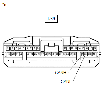
(b) Disconnect the R39 clearance warning ECU assembly connector.
(c) Measure the resistance according to the value(s) in the table below.
Standard Resistance:
|
Tester Connection |
Condition |
Specified Condition |
|---|---|---|
|
R39-37 (CANH) - R39-38 (CANL) |
Cable disconnected from negative (-) auxiliary battery terminal |
54 to 69 Ω |
| OK |
|
| NG |
|
REPAIR OR REPLACE CAN BUS WIRE (CLEARANCE WARNING ECU ASSEMBLY - NO. 36 CAN JUNCTION CONNECTOR) |
|
17. |
CHECK FOR SHORT IN CAN BUS (BLIND SPOT MONITOR SENSOR LH (A) CONNECTION MAIN LINE) |
(a) Disconnect the No. 36 CAN junction connector.
|
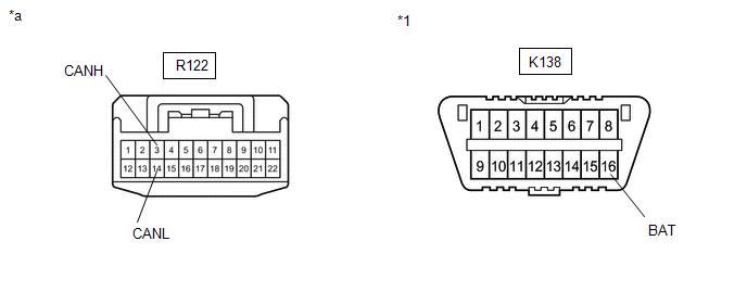
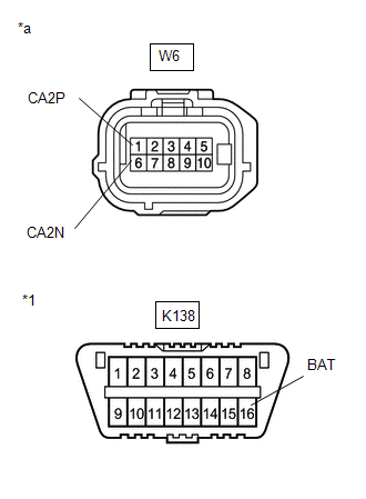
*a |
Front view of wire harness connector (to No. 36 CAN Junction Connector) |
*1 |
DLC3 |
(b) Measure the resistance according to the value(s) in the table below.
Standard Resistance:
|
Tester Connection |
Condition |
Specified Condition |
|---|---|---|
|
R122-3 (CANH) - Body ground |
Disconnect cable from negative (-) auxiliary battery terminal |
200 Ω or higher |
|
R122-14 (CANL) - Body ground |
Disconnect cable from negative (-) auxiliary battery terminal |
200 Ω or higher |
|
R122-3 (CANH) - K138-16 (BAT) |
Disconnect cable from negative (-) auxiliary battery terminal |
6 kΩ or higher |
|
R122-14 (CANL) - K138-16 (BAT) |
Disconnect cable from negative (-) auxiliary battery terminal |
6 kΩ or higher |
HINT:
Check for short that was confirmed to be a malfunction by confirming symptoms.
| NG |
|
|
|
18. |
CHECK FOR SHORT IN CAN BUS (BLIND SPOT MONITOR SENSOR RH (B) CONNECTION MAIN LINE) |
(a) Disconnect the No. 36 CAN junction connector.
|
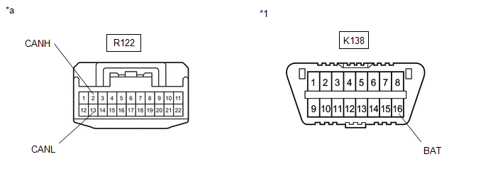
*a |
Front view of wire harness connector (to No. 36 CAN Junction Connector) |
*1 |
DLC3 |
(b) Measure the resistance according to the value(s) in the table below.
Standard Resistance:
|
Tester Connection |
Condition |
Specified Condition |
|---|---|---|
|
R122-2 (CANH) - Body ground |
Disconnect cable from negative (-) auxiliary battery terminal |
200 Ω or higher |
|
R122-13 (CANL) - Body ground |
Disconnect cable from negative (-) auxiliary battery terminal |
200 Ω or higher |
|
R122-2 (CANH) - K138-16 (BAT) |
Disconnect cable from negative (-) auxiliary battery terminal |
6 kΩ or higher |
|
R122-13 (CANL) - K138-16 (BAT) |
Disconnect cable from negative (-) auxiliary battery terminal |
6 kΩ or higher |
HINT:
Check for short that was confirmed to be a malfunction by confirming symptoms.
| NG |
|
|
|
19. |
CHECK FOR SHORT IN CAN BUS (CLEARANCE WARNING ECU ASSEMBLY CONNECTION BRANCH LINE) |
(a) Reconnect the No. 36 CAN junction connector.
|
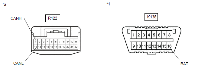
*a |
Front view of wire harness connector (to No. 36 CAN Junction Connector) |
*1 |
DLC3 |
(b) Measure the resistance according to the value(s) in the table below.
Standard Resistance:
|
Tester Connection |
Condition |
Specified Condition |
|---|---|---|
|
R122-1 (CANH) - Body ground |
Disconnect cable from negative (-) auxiliary battery terminal |
200 Ω or higher |
|
R122-12 (CANL) - Body ground |
Disconnect cable from negative (-) auxiliary battery terminal |
200 Ω or higher |
|
R122-1 (CANH) - K138-16 (BAT) |
Disconnect cable from negative (-) auxiliary battery terminal |
6 kΩ or higher |
|
R122-12 (CANL) - K138-16 (BAT) |
Disconnect cable from negative (-) auxiliary battery terminal |
6 kΩ or higher |
HINT:
Check for short that was confirmed to be a malfunction by confirming symptoms.
| OK |
|
REPLACE NO. 36 CAN JUNCTION CONNECTOR |
|
|
20. |
CHECK FOR SHORT IN CAN BUS (CLEARANCE WARNING ECU ASSEMBLY) |
|
(a) Reconnect the R122 No. 36 CAN junction connector. |
|
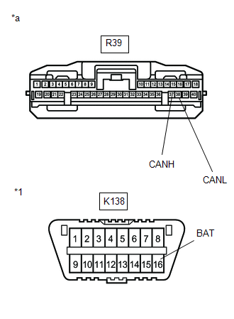
(b) Disconnect the connector of the clearance warning ECU assembly.
(c) Measure the resistance according to the value(s) in the table below.
Standard Resistance:
|
Tester Connection |
Condition |
Specified Condition |
|---|---|---|
|
R39-37 (CANH) - Body ground |
Disconnect cable from negative (-) auxiliary battery terminal |
200 Ω or higher |
|
R39-38 (CANL) - Body ground |
Disconnect cable from negative (-) auxiliary battery terminal |
200 Ω or higher |
|
R39-37 (CANH) - K138-16 (BAT) |
Disconnect cable from negative (-) auxiliary battery terminal |
6 kΩ or higher |
|
R39-38 (CANL) - K138-16 (BAT) |
Disconnect cable from negative (-) auxiliary battery terminal |
6 kΩ or higher |
| OK |
|
| NG |
|
REPAIR OR REPLACE CAN BUS BRANCH LINE OR CONNECTOR (CLEARANCE WARNING ECU ASSEMBLY - NO. 36 CAN JUNCTION CONNECTOR) |
|
21. |
CHECK FOR SHORT IN CAN BUS (BLIND SPOT MONITOR SENSOR RH (B)) |
|
(a) Reconnect the R122 No. 36 CAN junction connector. |
|

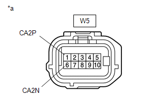
(b) Disconnect the connector of the blind spot monitor sensor RH (B).
(c) Measure the resistance according to the value(s) in the table below.
Standard Resistance:
|
Tester Connection |
Condition |
Specified Condition |
|---|---|---|
|
W5-1 (CA2P) - Body ground |
Disconnect cable from negative (-) auxiliary battery terminal |
200 Ω or higher |
|
W5-6 (CA2N) - Body ground |
Disconnect cable from negative (-) auxiliary battery terminal |
200 Ω or higher |
|
W5-1 (CA2P) - K138-16 (BAT) |
Disconnect cable from negative (-) auxiliary battery terminal |
6 kΩ or higher |
|
W5-6 (CA2N) - K138-16 (BAT) |
Disconnect cable from negative (-) auxiliary battery terminal |
6 kΩ or higher |
| OK |
|
| NG |
|
REPAIR OR REPLACE CAN BUS MAIN LINE OR CONNECTOR (BLIND SPOT MONITOR SENSOR RH (B) - NO. 36 CAN JUNCTION CONNECTOR) |
|
22. |
CHECK FOR SHORT IN CAN BUS (BLIND SPOT MONITOR SENSOR LH (A)) |
|
(a) Reconnect the R122 No. 36 CAN junction connector. |
|
(b) Disconnect the connector of the blind spot monitor sensor LH (A).
(c) Measure the resistance according to the value(s) in the table below.
Standard Resistance:
|
Tester Connection |
Condition |
Specified Condition |
|---|---|---|
|
W6-1 (CA2P) - Body ground |
Disconnect cable from negative (-) auxiliary battery terminal |
200 Ω or higher |
|
W6-6 (CA2N) - Body ground |
Disconnect cable from negative (-) auxiliary battery terminal |
200 Ω or higher |
|
W6-1 (CA2P) - K138-16 (BAT) |
Disconnect cable from negative (-) auxiliary battery terminal |
6 kΩ or higher |
|
W6-6 (CA2N) - K138-16 (BAT) |
Disconnect cable from negative (-) auxiliary battery terminal |
6 kΩ or higher |
| OK |
|
| NG |
|
REPAIR OR REPLACE CAN BUS MAIN LINE OR CONNECTOR (BLIND SPOT MONITOR SENSOR LH (A) - NO. 36 CAN JUNCTION CONNECTOR) |
|
|
|