| Last Modified: 02-14-2025 | 6.11:8.1.0 | Doc ID: RM100000001RX0R |
| Model Year Start: 2021 | Model: Camry HV | Prod Date Range: [10/2020 - ] |
| Title: CRUISE CONTROL: DYNAMIC RADAR CRUISE CONTROL SYSTEM: P057162; Brake Switch "A" Signal Compare Failure; 2021 - 2024 MY Camry HV [10/2020 - ] | ||
|
DTC |
P057162 |
Brake Switch "A" Signal Compare Failure |
DESCRIPTION
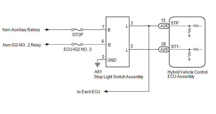
When the brake pedal is depressed, the stop light switch assembly outputs a signal to the hybrid vehicle control ECU assembly. The hybrid vehicle control ECU assembly uses this signal to control cancellation of vehicle speed by the dynamic radar cruise control. When the hybrid vehicle control ECU assembly determines that terminals STP and ST1- of the stop light switch assembly are both less than 1 V, DTC P057162 is stored.
|
DTC No. |
Detection Item |
DTC Detection Condition |
Trouble Area |
DTC Output from |
|---|---|---|---|---|
|
P057162 |
Brake Switch "A" Signal Compare Failure |
When the power switch is on (IG) and the dynamic radar cruise control system is operating, the hybrid vehicle control ECU assembly detects that the voltage at terminal STP and ST1- are both less than 1 V for approximately 0.5 seconds or more. |
|
Radar Cruise1 |
WIRING DIAGRAM

CAUTION / NOTICE / HINT
NOTICE:
PROCEDURE
|
1. |
CHECK HARNESS AND CONNECTOR (STOP LIGHT SWITCH ASSEMBLY - AUXILIARY BATTERY AND BODY GROUND) |
|
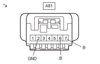
(a) Disconnect the stop light switch assembly connector. |
|
(b) Measure the resistance according to the value(s) in the table below.
Standard Resistance:
|
Tester Connection |
Condition |
Specified Condition |
|---|---|---|
|
A81-2 (GND) - Body ground |
Always |
Below 1 Ω |
(c) Measure the voltage according to the value(s) in the table below.
Standard Voltage:
|
Tester Connection |
Condition |
Specified Condition |
|---|---|---|
|
A81-7 (B) - Body ground |
Power switch off |
11 to 14 V |
|
A81-6 (B) - Body ground |
Power switch on (IG) |
11 to 14 V |
|
Power switch off |
Below 1 V |
| NG |

|
REPAIR OR REPLACE HARNESS OR CONNECTOR |
|
|
2. |
INSPECT STOP LIGHT SWITCH ASSEMBLY |
| NG |

|
|
|
3. |
CHECK HARNESS AND CONNECTOR (STOP LIGHT SWITCH ASSEMBLY - HYBRID VEHICLE CONTROL ECU ASSEMBLY) |
(a) Disconnect the A81 stop light switch assembly connector.
(b) Disconnect the A28 and A29 hybrid vehicle control ECU assembly connectors.
(c) Disconnect each ECU connector.
(d) Measure the resistance according to the value(s) in the table below.
Standard Resistance:
|
Tester Connection |
Condition |
Specified Condition |
|---|---|---|
|
A81-3 (L) - A28-15 (STP) |
Always |
Below 1 Ω |
|
A81-5 (L) - A29-28 (ST1-) |
Always |
Below 1 Ω |
|
A81-3 (L) or A28-15 (STP) - Body ground |
Always |
10 kΩ or higher |
|
A81-5 (L) or A29-28 (ST1-) - Body ground |
Always |
10 kΩ or higher |
| OK |

|
| NG |

|
REPAIR OR REPLACE HARNESS OR CONNECTOR |
|
|
|
![2020 - 2022 MY Camry HV [09/2019 - 08/2022]; THEFT DETERRENT / KEYLESS ENTRY: SMART KEY SYSTEM (for Start Function): REGISTRATION](/t3Portal/stylegraphics/info.gif)

