- Replacement of throttle body assembly
- Cleaning the deposits from the throttle body assembly
- Gas leak from exhaust system is repaired
| Last Modified: 02-14-2025 | 6.11:8.1.0 | Doc ID: RM100000001R9OA |
| Model Year Start: 2021 | Model: Camry HV | Prod Date Range: [10/2020 - ] |
| Title: A25A-FXS (INTAKE / EXHAUST): INTAKE MANIFOLD: REMOVAL; 2021 - 2024 MY Camry HV [10/2020 - ] | ||
REMOVAL
CAUTION / NOTICE / HINT
The necessary procedures (adjustment, calibration, initialization or registration) that must be performed after parts are removed and installed, or replaced during intake manifold removal/installation are shown below.
Necessary Procedures After Parts Removed/Installed/Replaced
|
Replaced Part or Performed Procedure |
Necessary Procedure |
Effect/Inoperative Function when Necessary Procedure not Performed |
Link |
|---|---|---|---|
|
|
Inspection After Repair |
|
|
NOTICE:
This procedure includes the removal of small-head bolts. Refer to Small-Head Bolts of Basic Repair Hint to identify the small-head bolts.
Click here
![2020 - 2024 MY Camry HV [09/2019 - ]; INTRODUCTION: REPAIR INSTRUCTION: PRECAUTION](/t3Portal/stylegraphics/info.gif)
PROCEDURE
1. REMOVE THROTTLE BODY WITH MOTOR ASSEMBLY
Click here
2. DISCONNECT ENGINE WIRE
Click here
3. REMOVE NO. 1 EGR PIPE SUB-ASSEMBLY
Click here
4. REMOVE E.F.I. VACUUM SENSOR ASSEMBLY (MANIFOLD ABSOLUTE PRESSURE SENSOR)
Click here
5. REMOVE PURGE VALVE (PURGE VSV)
Click here
6. DISCONNECT ENGINE WIRE
|
(a) Disconnect the No. 5 engine wire connector. |
|
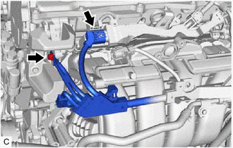
(b) Remove the bolt and disconnect the engine wire from the cylinder head sub-assembly.
|
(c) Remove the bolt. |
|
(d) Disengage the wire harness clamp and disconnect the engine wire from the intake manifold.
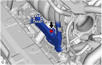
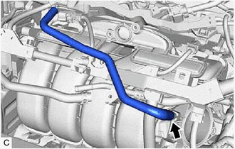
7. DISCONNECT NO. 3 WATER BY-PASS PIPE
|
(a) Slide the clip and disconnect the No. 5 water by-pass hose from the No. 3 water by-pass pipe. |
|
(b) Using an 8 mm socket wrench, remove the bolt and disconnect the No. 3 water by-pass pipe from the intake manifold.
8. REMOVE NO. 2 WATER BY-PASS PIPE
|
(a) Disengage the wire harness clamp and disconnect the HV air conditioning wire. |
|
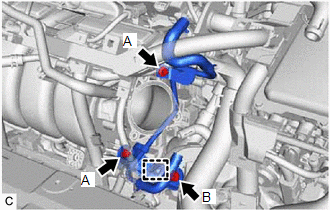
(b) Using an 8 mm socket wrench, remove the 2 bolts (A) and separate the No. 2 water by-pass pipe from the intake manifold.
(c) Remove the bolt (B) and No. 2 water by-pass pipe from the cylinder block sub-assembly.
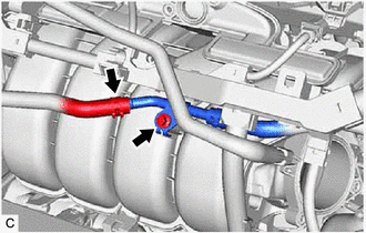
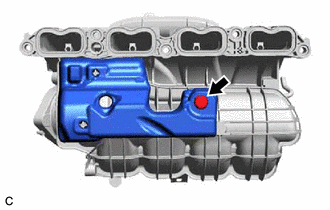
9. REMOVE NO. 2 FUEL VAPOR FEED HOSE
|
(a) Remove the No. 2 fuel vapor feed hose from the intake manifold. |
|
10. REMOVE INTAKE MANIFOLD
|
(a) w/o Stud Bolt: (1) Remove the 5 bolts and intake manifold from the cylinder head sub-assembly. |
|
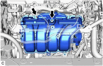
(b) w/ Stud Bolt:
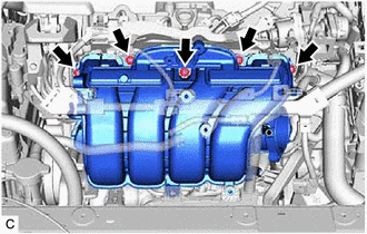
(1) Remove the 3 bolts and 2 nuts.
|
(2) Using an E8 "TORX" socket wrench, remove the 2 stud bolts and intake manifold from the cylinder head sub-assembly. |
|
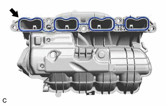
11. REMOVE NO. 1 INTAKE MANIFOLD TO HEAD GASKET
|
(a) Remove the No. 1 intake manifold to head gasket from the intake manifold. |
|
12. REMOVE NO. 1 ENGINE COVER
|
(a) Remove the clip and No. 1 engine cover. |
|
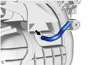
13. REMOVE VACUUM HOSE
|
(a) Remove the vacuum hose from the intake manifold. |
|
|
|
|