| Last Modified: 02-14-2025 | 6.11:8.1.0 | Doc ID: RM100000001KMAJ |
| Model Year Start: 2020 | Model: Camry HV | Prod Date Range: [09/2019 - ] |
| Title: HYBRID / BATTERY CONTROL: HYBRID CONTROL SYSTEM (for LITHIUM-ION BATTERY): Shift Paddle Switch Circuit; 2020 - 2024 MY Camry HV [09/2019 - ] | ||
|
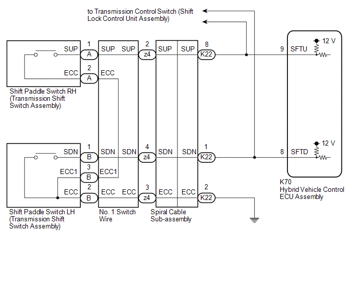
Shift Paddle Switch Circuit |
DESCRIPTION
Moving the shift lever to S enables the shift range to be selected. The shift range can be selected by operating the "+" or "-" shift paddle switch.
WIRING DIAGRAM
CAUTION / NOTICE / HINT
NOTICE:
After turning the power switch off, waiting time may be required before disconnecting the cable from the negative (-) auxiliary battery terminal. Therefore, make sure to read the disconnecting the cable from the negative (-) auxiliary battery terminal notices before proceeding with work.
Click here
![2020 - 2024 MY Camry HV [09/2019 - ]; INTRODUCTION: REPAIR INSTRUCTION: PRECAUTION](/t3Portal/stylegraphics/info.gif)
PROCEDURE
|
1. |
READ VALUE USING TECHSTREAM (SPORTS SHIFT UP SIGNAL, SPORTS SHIFT DOWN SIGNAL) |
(a) Connect the Techstream to the DLC3.
(b) Turn the power switch on (IG).
(c) Enter the following menus: Powertrain / Hybrid Control / Data List / Sports Shift UP Signal, Sports Shift DOWN Signal.
Powertrain > Hybrid Control > Data List
|
Tester Display |
|---|
|
Sports Shift UP Signal |
|
Sports Shift DOWN Signal |
(d) Read the values displayed on the Techstream.
|
Result |
Proceed to |
|---|---|
|
The Techstream display changes according to the shift paddle switch (transmission shift switch assembly) operation. |
A |
|
The Techstream display does not change according to the shift paddle switch (transmission shift switch assembly) operation. |
B |
(e) Turn the power switch off.
| A |

|
|

|
2. |
CHECK HARNESS AND CONNECTOR (SHIFT PADDLE SWITCH CIRCUIT) |
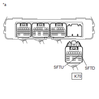
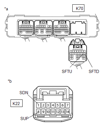
(a) Disconnect the K70 hybrid vehicle control ECU assembly connector.
(b) Disconnect the K29 transmission control switch (shift lock control unit assembly) connector.
|
(c) Measure the resistance according to the value(s) in the table below when the shift paddle switch (transmission shift switch assembly) is moved to each position. Standard Resistance:
|
|
(d) Reconnect the K29 transmission control switch (shift lock control unit assembly) connector.
(e) Reconnect the K70 hybrid vehicle control ECU assembly connector.
| OK |
|
REPLACE HYBRID VEHICLE CONTROL ECU ASSEMBLY
|
|
|
3. |
CHECK HARNESS AND CONNECTOR (SPIRAL CABLE SUB-ASSEMBLY - BODY GROUND) |
|
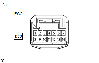
(a) Disconnect the K22 spiral cable sub-assembly connector. |
|
(b) Measure the resistance according to the value(s) in the table below.
Standard Resistance (Open):
|
Tester Connection |
Condition |
Specified Condition |
|---|---|---|
|
K22-2 (ECC) - Body ground |
Always |
Below 1 Ω |
(c) Reconnect the K22 spiral cable sub-assembly connector.
| NG |
|
REPAIR OR REPLACE HARNESS OR CONNECTOR |
|
|
4. |
CHECK HARNESS AND CONNECTOR (SPIRAL CABLE SUB-ASSEMBLY - HYBRID VEHICLE CONTROL ECU ASSEMBLY) |
(a) Disconnect the K70 hybrid vehicle control ECU assembly connector.
(b) Disconnect the K22 spiral cable with sensor sub-assembly connector.
|
(c) Measure the resistance according to the value(s) in the table below. Standard Resistance:
|
|
(d) Reconnect the K22 spiral cable with sensor sub-assembly connector.
(e) Reconnect the K70 hybrid vehicle control ECU assembly connector.
| NG |
|
REPAIR OR REPLACE HARNESS OR CONNECTOR |
|
|
5. |
INSPECT SPIRAL CABLE SUB-ASSEMBLY |
(a) Inspect the spiral cable sub-assembly.
Click here
| NG |
|
REPLACE SPIRAL CABLE SUB-ASSEMBLY
|
|
|
6. |
INSPECT SHIFT PADDLE SWITCH LH (TRANSMISSION SHIFT SWITCH ASSEMBLY) |
(a) Inspect the shift paddle switch LH (transmission shift switch assembly).
Click here
| NG |
|
REPLACE SHIFT PADDLE SWITCH LH (TRANSMISSION SHIFT SWITCH ASSEMBLY)
|
|
|
7. |
INSPECT SHIFT PADDLE SWITCH RH (TRANSMISSION SHIFT SWITCH ASSEMBLY) |
(a) Inspect the shift paddle switch RH (transmission shift switch assembly).
Click here
| NG |
|
REPLACE SHIFT PADDLE SWITCH RH (TRANSMISSION SHIFT SWITCH ASSEMBLY)
|
|
|
8. |
INSPECT NO. 1 SWITCH WIRE |
(a) Disconnect the z4 No. 1 switch wire connector.
|
(b) Measure the resistance according to the value(s) in the table below. Standard Resistance:
|
|
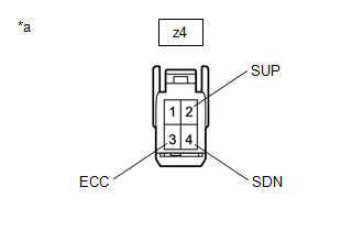
(c) Reconnect the z4 No. 1 switch wire connector.
| OK |
|
| NG |
|
REPLACE NO. 1 SWITCH WIRE
|
|
|
|