- Between A30-3 (CA2H) and A30-1 (SGND)
- Between A30-5 (CA1P) and A30-1 (SGND)
| Last Modified: 02-14-2025 | 6.11:8.1.0 | Doc ID: RM100000001EU5W |
| Model Year Start: 2019 | Model: Camry HV | Prod Date Range: [09/2018 - 10/2020] |
| Title: CRUISE CONTROL: DYNAMIC RADAR CRUISE CONTROL SYSTEM: TERMINALS OF ECU; 2019 - 2020 MY Camry HV [09/2018 - 10/2020] | ||
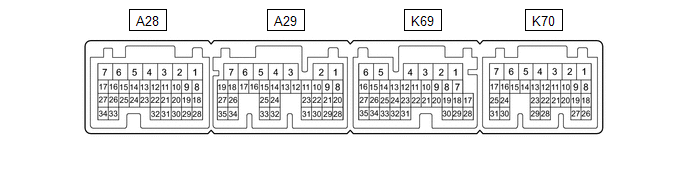
TERMINALS OF ECU
CHECK HYBRID VEHICLE CONTROL ECU ASSEMBLY
|
Terminal No. (Symbols) |
Wiring Color |
Terminal Description |
Condition |
Specified Condition |
|---|---|---|---|---|
|
K70-3 (BATT) - K69-6 (E1) |
B - W-B |
Constant power source |
Always |
11 to 14 V |
|
A29-26 (DB1) - K69-6 (E1) |
W - W-B |
D shift position signal |
Power switch on (IG), shift lever in D |
7.5 to 14 V |
|
Power switch on (IG), shift lever not in D |
Below 1 V |
|||
|
A29-14 (DB2) - K69-6 (E1) |
V - W-B |
D shift position signal |
Power switch on (IG), shift lever in D |
7.5 to 14 V |
|
Power switch on (IG), shift lever not in D |
Below 1 V |
|||
|
A70-1 (M) - K69-6 (E1) |
B - W-B |
S shift position signal |
Power switch on (IG), shift lever in S |
11 to 14 V |
|
Power switch on (IG), shift lever not in S |
Below 1 V |
|||
|
A28-15 (STP) - K69-6 (E1) |
LA-G - W-B |
Stop light switch signal |
Brake pedal depressed |
7.5 to 14 V |
|
Brake pedal released |
Below 1 V |
|||
|
K69-28 (CCS) - K69-6 (E1) |
GR - W-B |
Steering pad switch circuit |
Cruise control switch not pushed |
1 MΩ or higher |
|
Cruise control main switch pushed |
Below 2.5 Ω |
|||
|
+RES switch pushed |
617 to 643 Ω |
|||
|
-SET switch pushed |
1509 to 1571 Ω |
|||
|
CANCEL switch pushed |
235 to 245 Ω |
|||
|
A29-28 (ST1-) - K69-6 (E1) |
LG - W-B |
Stop light switch signal |
Power switch on (IG), brake pedal depressed |
Below 1 V |
|
Power switch on (IG), brake pedal released |
7.5 to 14 V |
|||
|
K70-8 (SFTD) - K69-6 (E1) |
G - W-B*1 W - W-B*2 |
Down-shift position switch signal |
Power switch on (IG), shift lever in S |
11 to 14 V |
|
Power switch on (IG), shift lever in "-" |
Below 1 V |
|||
|
K70-9 (SFTU) - K69-6 (E1) |
L - W-B*1 LG - W-B*2 |
Up-shift position switch signal |
Power switch on (IG), shift lever in S |
11 to 14 V |
|
Power switch on (IG), shift lever in "+" |
Below 1 V |
-
*1: w/o Shift Paddle Switch
*2: w/ Shift Paddle Switch

|
Terminal No. (Symbol) |
Wiring Color |
Terminal Description |
Condition |
Specified Condition |
|---|---|---|---|---|
|
A30-1 (SGND) - Body ground |
W-B - Body ground |
Ground |
Always |
Below 1 Ω |
|
A30-2 (CA2L) - A30-1 (SGND) |
W - W-B |
CAN communication signal |
Power switch on (IG) |
Pulse generation (See waveform 2) |
|
A30-3 (CA2H) - A30-1 (SGND) |
R - W-B |
CAN communication signal |
Power switch on (IG) |
Pulse generation (See waveform 1) |
|
A30-5 (CA1P) - A30-1 (SGND) |
G - W-B |
CAN communication signal |
Power switch on (IG) |
Pulse generation (See waveform 1) |
|
A30-6 (CA1N) - A30-1 (SGND) |
W - W-B |
CAN communication signal |
Power switch on (IG) |
Pulse generation (See waveform 2) |
|
A30-8 (IGB) - A30-1 (SGND) |
B - W-B |
Power source |
Power switch on (IG) |
11 to 14 V |
CHECK MILLIMETER WAVE RADAR SENSOR ASSEMBLY
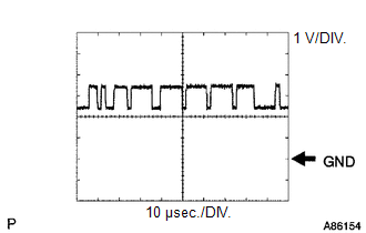
(a) Waveform 1
(1) CAN communication signal
|
Item |
Content |
|---|---|
|
Tester Connection |
|
|
Tool Setting |
1 V/DIV., 10 μsec./DIV. |
|
Condition |
Power switch on (IG) |
HINT:
The waveform varies depending on the CAN communication signal.
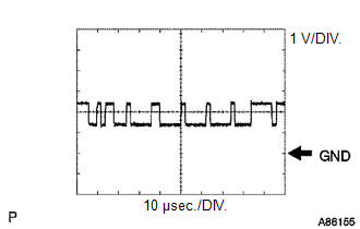
(b) Waveform 2
(1) CAN communication signal
|
Item |
Content |
|---|---|
|
Tester Connection |
|
|
Tool Setting |
1 V/DIV., 10 μsec./DIV. |
|
Condition |
Power switch on (IG) |
HINT:
The waveform varies depending on the CAN communication signal.
NOTICE:
- DTCs may be output when connectors are disconnected during inspection. Therefore, be sure to clear the DTCs using the Techstream once the inspection has been completed.
- Do not apply excessive force to the V6 forward recognition camera connector.

CHECK FORWARD RECOGNITION CAMERA
|
Terminal No. (Symbol) |
Wiring Color |
Terminal Description |
Condition |
Specified Condition |
|---|---|---|---|---|
|
V6-7 (IGB) - V6-10 (GND) |
LA-P - LA |
Power source |
Power switch on (IG) |
11 to 14 V |
|
Power switch off |
Below 1 V |
|||
|
V6-5 (CA1P) - V6-10 (GND) |
L - LA |
CAN communication signal |
Power switch on (IG) |
Pulse generation (See waveform 1) |
|
V6-11 (CA1N) - V6-10 (GND) |
W - LA |
CAN communication signal |
Power switch on (IG) |
Pulse generation (See waveform 2) |
|
V6-6 (CANH) - V6-10 (GND) |
G - LA |
CAN communication signal |
Power switch on (IG) |
Pulse generation (See waveform 1) |
|
V6-12 (CANL) - V6-10 (GND) |
W - LA |
CAN communication signal |
Power switch on (IG) |
Pulse generation (See waveform 2) |
|
V6-3 (LKSW) - V6-10 (GND) |
V - LA |
Vehicle-to-vehicle distance control switch signal |
Power switch on (IG), vehicle-to-vehicle distance control switch not pushed |
4.75 to 5.25 V |
|
Power switch on (IG), vehicle-to-vehicle distance control switch pushed |
Below 1 V |
|||
|
V6-10 (GND) - Body ground |
LA - Body ground |
Ground |
Always |
Below 1 Ω |
(a) Waveform 1
(1) CAN communication signal
|
Item |
Content |
|---|---|
|
Tester Connection |
|
|
Tool Setting |
1 V/DIV., 10 μsec./DIV. |
|
Condition |
Power switch on (IG) |
HINT:
The waveform varies depending on the CAN communication signal.
(b) Waveform 2
(1) CAN communication signal
|
Item |
Content |
|---|---|
|
Tester Connection |
|
|
Tool Setting |
1 V/DIV., 10 μsec./DIV. |
|
Condition |
Power switch on (IG) |
HINT:
The waveform varies depending on the CAN communication signal.
|
|
|