| Last Modified: 02-14-2025 | 6.11:8.1.0 | Doc ID: RM10000000163YO |
| Model Year Start: 2018 | Model: Camry HV | Prod Date Range: [07/2017 - 10/2020] |
| Title: PARK ASSIST / MONITORING: PANORAMIC VIEW MONITOR SYSTEM: ECU Power Source Circuit; 2018 - 2020 MY Camry HV [07/2017 - 10/2020] | ||
|
ECU Power Source Circuit |
DESCRIPTION
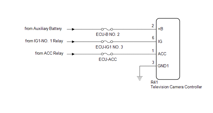
This circuit is the power source circuit to operate the television camera controller. The television camera controller controls the panoramic view monitor system.
WIRING DIAGRAM
CAUTION / NOTICE / HINT
NOTICE:
Inspect the fuse for circuits related to this system before performing the following inspection procedure.
HINT:
If the television camera controller does not operate due to a power source problem, other system DTCs may be stored due to a CAN communication interruption.
PROCEDURE
|
1. |
CHECK HARNESS AND CONNECTOR (TELEVISION CAMERA CONTROLLER - BODY GROUND) |
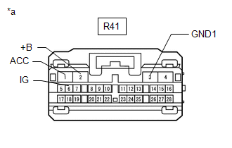
(a) Disconnect the R41 television camera controller connector.
(b) Measure the resistance according to the value(s) in the table below.
Standard Resistance:
|
Tester Connection |
Condition |
Specified Condition |
|---|---|---|
|
R41-3 (GND1) - Body ground |
Always |
Below 1 Ω |
| NG |

|
REPAIR OR REPLACE HARNESS OR CONNECTOR |
|

|
2. |
CHECK HARNESS AND CONNECTOR (TELEVISION CAMERA CONTROLLER POWER SOURCE) |
(a) Disconnect the R41 television camera controller connector.
|
(b) Measure the voltage according to the value(s) in the table below. Standard Voltage:
|
|
| OK |
|
PROCEED TO NEXT SUSPECTED AREA SHOWN IN PROBLEM SYMPTOMS TABLE |
| NG |
|
REPAIR OR REPLACE HARNESS OR CONNECTOR |
|
|
|