| Last Modified: 02-14-2025 | 6.11:8.1.0 | Doc ID: RM100000001628F |
| Model Year Start: 2018 | Model: Camry HV | Prod Date Range: [07/2017 - ] |
| Title: A25A-FXS (FUEL): FUEL INJECTOR (for Direct Injection): INSTALLATION; 2018 - 2024 MY Camry HV [07/2017 - ] | ||
INSTALLATION
CAUTION / NOTICE / HINT
NOTICE:
This procedure includes the installation of small-head bolts. Refer to Small-Head Bolts of Basic Repair Hint to identify the small-head bolts.
Click here
![2018 - 2019 MY Camry HV [07/2017 - 09/2019]; INTRODUCTION: REPAIR INSTRUCTION: PRECAUTION](/t3Portal/stylegraphics/info.gif)
PROCEDURE
1. INSTALL FUEL INJECTOR SEAL
|
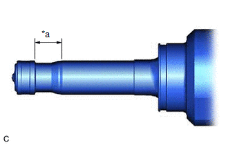
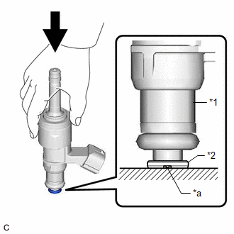
(a) Apply engine conditioner to the area shown in the illustration. Using a piece of cloth, clean carbon deposits from the direct fuel injector assembly and its grooves. NOTICE:
|
|
|
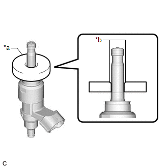
(b) Apply engine oil to the direct fuel injector assembly contact surface of SST (guide), then attach SST (guide) to the direct fuel injector assembly with the chamfer facing the tip of the direct fuel injector assembly as shown in the illustration. SST: 09260-39030 09261-03030 |
|
|
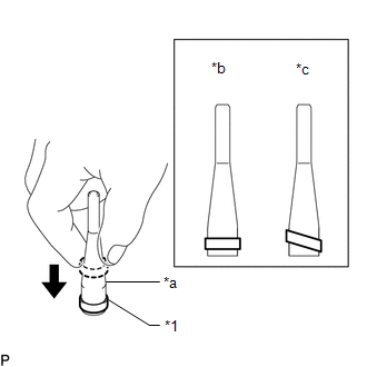
(c) Install a new fuel injector seal to SST (holder). SST: 09260-39030 09261-03011 NOTICE: Be careful not to install the fuel injector seal to SST (holder) at an angle. Doing so will stretch the fuel injector seal. |
|
|
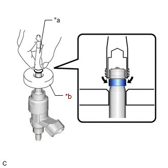
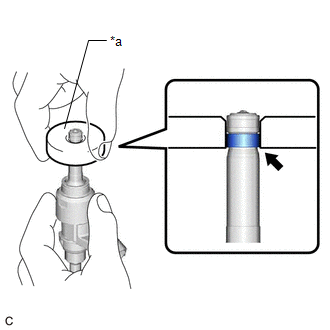
(d) Install SST (holder) with the fuel injector seal to the tip of the direct fuel injector assembly. Slide the fuel injector seal downward into the direct fuel injector assembly groove with your fingers as shown in the illustration. SST: 09260-39030 09261-03011 09261-03030 HINT: Check that the fuel injector seal is seated in the direct fuel injector assembly groove as shown in the illustration. |
|
|
(e) Slowly slide SST (guide) toward the tip of the direct fuel injector assembly. When the direct fuel injector assembly contact surface of SST (guide) aligns with the fuel injector seal as shown in the illustration, hold the position for 10 seconds or more to fully seat the fuel injector seal into the direct fuel injector assembly groove. SST: 09260-39030 09261-03030 NOTICE: Make sure the fuel injector seal is not pinched between SST (guide) and the edge of the direct fuel injector assembly groove. Replace the fuel injector seal if it becomes damaged. HINT:
|
|
|
(f) After installing the fuel injector seals, check that they are not scratched, deformed or protruding from the direct fuel injector assembly groove. NOTICE: If a fuel injector seal is scratched, deformed or protruding from the groove, replace it with a new one. HINT: Use the same procedure to install the other fuel injector seals. |
|
2. INSTALL DIRECT FUEL INJECTOR ASSEMBLY
HINT:
Perform "Inspection After Repair" after replacing a direct fuel injector assembly.
Click here
|
(a) Install a new injector vibration insulator and a new C-ring to each direct fuel injector assembly. NOTICE:
|
|
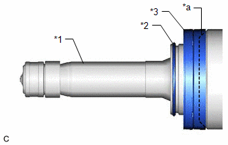
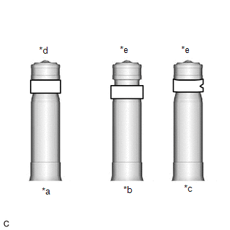
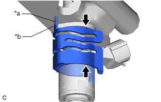
(b) Install a new O-ring and No. 1 fuel injector back-up ring to each direct fuel injector assembly as shown in the illustration.
|
*1 |
No. 1 Fuel Injector Back-up Ring |
*2 |
O-ring |
|
*a |
No. 1 Fuel Injector Back-up Ring Opening |
*b |
Overlapped |
|
*c |
Stretched |
*d |
Correct |
|
*e |
Incorrect |
- |
- |
NOTICE:
- Check that there is no foreign matter or damage on the O-ring groove of the direct fuel injector assembly.
- Make sure that the No. 1 fuel injector back-up ring is installed in the correct orientation.
- Make sure that the No. 1 fuel injector back-up ring and O-ring are installed in the correct order.
- Check that the opening of the No. 1 fuel injector back-up ring is not overlapped or stretched as shown in the illustration.
- After installing the O-ring, check that it is not contaminated with foreign matter and is not damaged.
|
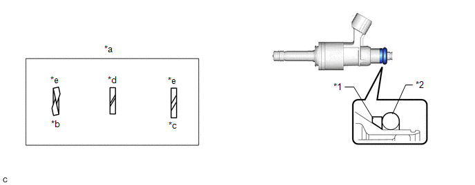
(c) With the notch of a new No. 3 fuel injector back-up ring facing downward, install the No. 3 fuel injector back-up ring to each direct fuel injector assembly as shown in the illustration. NOTICE:
|
|
(d) Install the nozzle holder clamp to each direct fuel injector assembly.
(e) Align the protrusion of the nozzle holder clamp with the positioning hole of the fuel delivery pipe and insert the direct fuel injector assembly.
|
*a |
Protrusion |
|
*b |
Positioning Hole |

|
No Gap |
NOTICE:
- Make sure that there is no foreign matter or damage inside the direct fuel injector assembly installation holes (fuel delivery pipe).
- Do not allow gasoline to get on the O-rings or inside the installation holes.
- If it is difficult to insert the direct fuel injector assembly, apply new engine oil to the chamfer of the direct fuel injector assembly installation hole of the fuel delivery pipe. Be careful not to allow the direct fuel injector assembly to fall out of the fuel delivery pipe.
- Do not tilt the direct fuel injector assembly when inserting it into the fuel delivery pipe.
- Check that there is no gap between the fuel delivery pipe and the nozzle holder clamp.
-
As direct fuel injector assemblies with different flow classification numbers are incompatible, make sure the 4 direct fuel injector assemblies have the same flow classification number (the number to the left of the QR code (1, 2, 3, 4, 5, 6, 7, 8 or 9)).
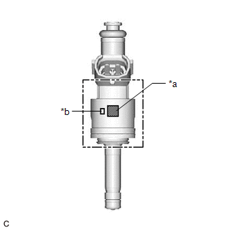
*a
QR Code
*b
Flow Classification Number
HINT:
When replacing the direct fuel injector assemblies for all cylinders, it is not necessary to use the same flow classification number as those currently installed to the vehicle. However, make sure to replace the direct fuel injector assemblies with new ones that all have the same flow classification number (1, 2, 3, 4, 5, 6, 7, 8 or 9).
3. INSTALL FUEL DELIVERY PIPE
NOTICE:
When replacing the fuel delivery pipe, it is necessary to replace the No. 1 fuel pipe sub-assembly with a new one.
(a) Apply lubricant to the direct fuel injector assembly installation holes of the cylinder head sub-assembly.
(b) Temporarily install the fuel delivery pipe to the cylinder head sub-assembly.
NOTICE:
- If a direct fuel injector assembly is dropped or the tip of a direct fuel injector assembly is struck, replace it with a new one.
- Check that there is no foreign matter or damage on the direct fuel injector assembly installation holes of the cylinder head sub-assembly.
- When installing the fuel delivery pipe, push it in evenly without tilting it.
|
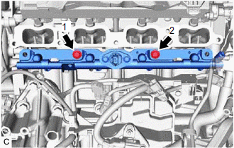
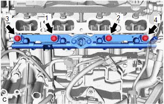
(c) Temporarily install the 2 bolts in the order shown in the illustration. |
|
|
(d) Install the fuel delivery pipe by uniformly tightening the 4 bolts in the order shown in the illustration. Torque: 28.5 N·m {291 kgf·cm, 21 ft·lbf} |
|
(e) Connect the 4 direct fuel injector assembly connectors.
(f) Engage the clamp to connect the sensor wire to the fuel delivery pipe.
(g) Connect the fuel pressure sensor connector.
4. TEMPORARILY INSTALL NO. 1 FUEL PIPE SUB-ASSEMBLY
NOTICE:
Do not damage the seals of the union nuts of the No. 1 fuel pipe sub-assembly.
(a) for Cylinder Head Cover Sub-assembly Connection Type:
(1) Temporarily install the bolt.
(b) Temporarily install the No. 1 fuel pipe sub-assembly to the fuel delivery pipe and tighten the union nut by hand.
(c) Temporarily install the No. 1 fuel pipe sub-assembly to the fuel pump assembly and tighten the union nut by hand.
5. INSTALL NO. 1 FUEL PIPE SUB-ASSEMBLY
(a) Tighten the 2 bolts.
Torque:
28.5 N·m {291 kgf·cm, 21 ft·lbf}
(b) for EGR Valve Bracket Connection Type:
|
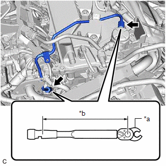
(1) Using a 17 mm union nut wrench, tighten the union nut on the fuel delivery pipe side of the No. 1 fuel pipe sub-assembly. Torque: Specified tightening torque : 35 N·m {357 kgf·cm, 26 ft·lbf} NOTICE: Do not adjust the torque in the loosening direction. HINT:
|
|
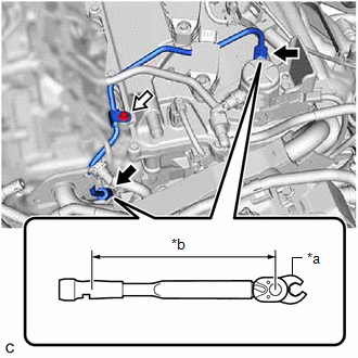
(2) Using a 17 mm union nut wrench, tighten the union nut on the fuel pump assembly side of the No. 1 fuel pipe sub-assembly.
Torque:
Specified tightening torque :
35 N·m {357 kgf·cm, 26 ft·lbf}
NOTICE:
Do not adjust the torque in the loosening direction.
HINT:
-
Calculate the torque wrench reading when changing the fulcrum length of the torque wrench.
Click here
- When using a 17 mm union nut wrench (fulcrum length of 30 mm (1.18 in.)) + torque wrench (fulcrum length of 180 mm (7.09 in.)): 30 N*m (306 kgf*cm, 22 ft.*lbf)
(c) for Cylinder Head Cover Sub-assembly Connection Type:
(1) Using a 17 mm union nut wrench, tighten the union nut on the fuel delivery pipe side of the No. 1 fuel pipe sub-assembly.
|
*a |
17 mm Union Nut Wrench |
|
*b |
Torque Wrench Fulcrum Length |
|
|
Union Nut |

|
Bolt |
Torque:
Specified tightening torque :
35 N·m {357 kgf·cm, 26 ft·lbf}
NOTICE:
Do not adjust the torque in the loosening direction.
HINT:
-
Calculate the torque wrench reading when changing the fulcrum length of the torque wrench.
Click here
- When using a 17 mm union nut wrench (fulcrum length of 30 mm (1.18 in.)) + torque wrench (fulcrum length of 180 mm (7.09 in.)): 30 N*m (306 kgf*cm, 22 ft.*lbf)
(2) Using a 17 mm union nut wrench, tighten the union nut on the fuel pump assembly side of the No. 1 fuel pipe sub-assembly.
Torque:
Specified tightening torque :
35 N·m {357 kgf·cm, 26 ft·lbf}
NOTICE:
Do not adjust the torque in the loosening direction.
HINT:
-
Calculate the torque wrench reading when changing the fulcrum length of the torque wrench.
Click here
- When using a 17 mm union nut wrench (fulcrum length of 30 mm (1.18 in.)) + torque wrench (fulcrum length of 180 mm (7.09 in.)): 30 N*m (306 kgf*cm, 22 ft.*lbf)
(3) Using an 8 mm socket wrench, tighten the bolt.
Torque:
10 N·m {102 kgf·cm, 7 ft·lbf}
(d) Connect the ignition coil connector.
6. INSTALL INTAKE MANIFOLD
Click here
7. CONNECT CABLE TO NEGATIVE AUXILIARY BATTERY TERMINAL
NOTICE:
When disconnecting the cable, some systems need to be initialized after the cable is reconnected.
Click here
8. INSTALL LUGGAGE TRIM SERVICE HOLE COVER
Click here
9. INSPECT FOR FUEL LEAK
Click here
10. PERFORM INITIALIZATION
(a) Perform "Inspection After Repair" after replacing a direct fuel injector assembly.
Click here
|
|
|