| Last Modified: 02-14-2025 | 6.11:8.1.0 | Doc ID: RM1000000015HIU |
| Model Year Start: 2018 | Model: Camry HV | Prod Date Range: [07/2017 - ] |
| Title: BRAKE CONTROL / DYNAMIC CONTROL SYSTEMS: BRAKE ACTUATOR: INSTALLATION; 2018 - 2024 MY Camry HV [07/2017 - ] | ||
INSTALLATION
CAUTION / NOTICE / HINT
HINT:
The parking brake indicator light blinks (red) when the power switch is turned on after replacing the brake actuator assembly. Operate the electric parking brake switch assembly to turn off the parking brake indicator light.
PROCEDURE
1. INSTALL BRAKE ACTUATOR BOLT CUSHION
(a) Install the 3 brake actuator bolt cushions to the brake actuator bracket assembly.
(b) Install the 3 brake actuator case collars to the brake actuator bolt cushions.
NOTICE:
Make sure that the brake actuator case collars are in full contact with the brake actuator bolt cushions.
2. INSTALL BRAKE ACTUATOR ASSEMBLY
(a) Install the brake actuator assembly to the brake actuator bracket assembly with the 3 bolts.
Torque:
6.5 N·m {66 kgf·cm, 58 in·lbf}
NOTICE:
- Do not remove the hole plugs of a new brake actuator assembly before connecting the brake lines because the brake actuator assembly is filled with brake fluid.
- Do not hold the brake actuator assembly by the connector.
- Do not drop the brake actuator assembly when carrying it.
3. INSTALL BRAKE ACTUATOR WITH BRACKET
(a) Temporarily install the brake actuator with bracket to the vehicle body as shown in the illustration.
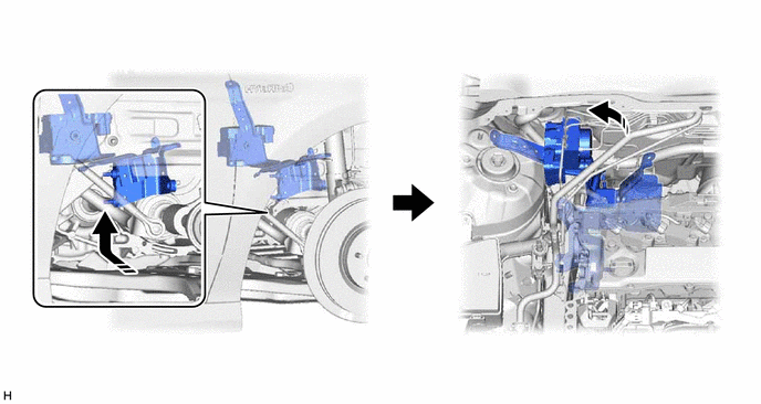
NOTICE:
- Do not kink or damage the brake lines.
- Do not allow any foreign matter such as dirt or dust to enter the brake lines from the connecting parts.
- Be careful not to allow any brake fluid to enter the connector.
- Do not hold the brake actuator assembly by the connector.
- Do not drop the brake actuator with bracket when carrying it.
HINT:
Install the brake actuator with bracket while avoiding the brake lines.
|
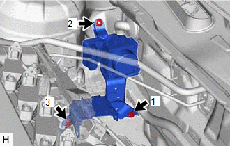
(b) Install the 2 bolts and nut in the order shown in the illustration. Torque: 19 N·m {194 kgf·cm, 14 ft·lbf} HINT: Install the 2 bolts from the bottom of the vehicle. |
|
|
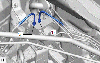
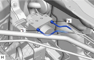
(c) Temporarily tighten the 2 brake lines to the correct positions on the brake actuator assembly as shown in the illustration. NOTICE:
|
|
|
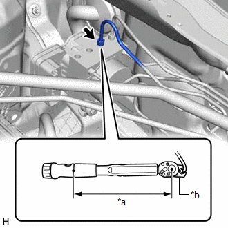
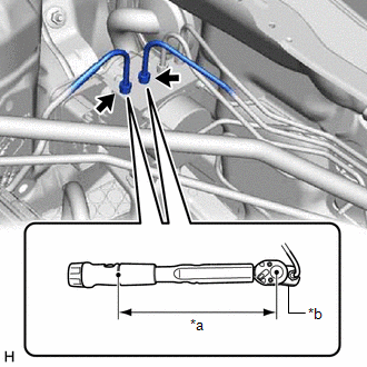
(d) Using a union nut wrench, fully tighten each brake line. Torque: Specified tightening torque : 15.2 N·m {155 kgf·cm, 11 ft·lbf} NOTICE: Do not kink or damage the brake lines. |
|
|
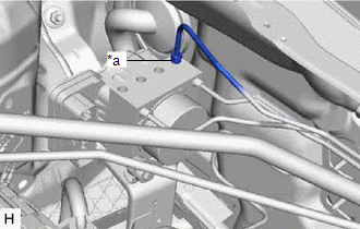
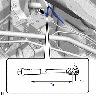
(e) Temporarily tighten the brake line to the correct position on the brake actuator assembly as shown in the illustration. NOTICE:
|
|
|
(f) Using a union nut wrench, fully tighten the brake line. Torque: Specified tightening torque : 15.2 N·m {155 kgf·cm, 11 ft·lbf} NOTICE: Do not kink or damage the brake line. |
|
|
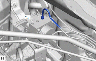
(g) Temporarily tighten the brake line to the correct position on the brake actuator assembly as shown in the illustration. NOTICE:
|
|
|
(h) Using a union nut wrench, fully tighten the brake line. Torque: Specified tightening torque : 15.2 N·m {155 kgf·cm, 11 ft·lbf} NOTICE: Do not kink or damage the brake line. |
|
|
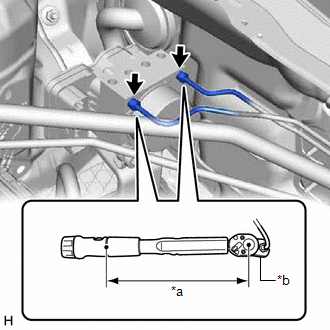
(i) Temporarily tighten the 2 brake lines to the correct positions on the brake actuator assembly as shown in the illustration. NOTICE:
|
|
|
(j) Using a union nut wrench, fully tighten each brake line. Torque: Specified tightening torque : 15.2 N·m {155 kgf·cm, 11 ft·lbf} NOTICE: Do not kink or damage the brake lines. |
|
(k) Connect the connector to the brake actuator assembly and lock the lock lever.
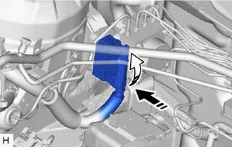

|
Connect the connector |

|
Lock the lock lever |
NOTICE:
- Make sure that the connector is locked securely.
- Make sure that the actuator connector can be connected smoothly.
- Do not allow water, oil or dirt to enter the connector.
4. INSTALL FRONT STABILIZER LINK ASSEMBLY RH
HINT:
Use the same procedure as for the LH side.
5. INSTALL FRONT WHEEL RH
6. INSTALL BRAKE BOOSTER PUMP ASSEMBLY
|
|
|
![2018 - 2019 MY Camry HV [07/2017 - 09/2019]; INTRODUCTION: REPAIR INSTRUCTION: PRECAUTION](/t3Portal/stylegraphics/info.gif)
